

High Frequency PCB Manufacturing for RF, Microwave & 5G Applications
Precision-built PTFE & Hybrid Stack-ups | Controlled Impedance | Up to 128 Layers
✅20+ Years Experience
✅Military & Aerospace Grade
✅Fast Turnaround for Prototypes & Volume
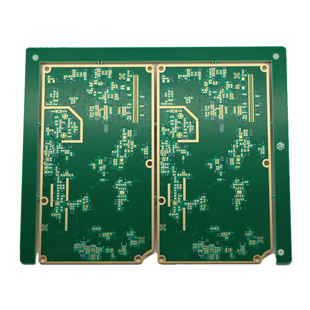
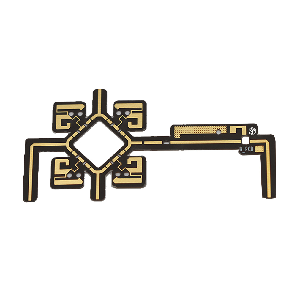
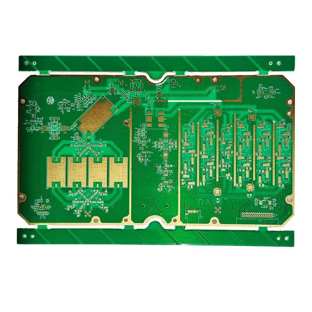
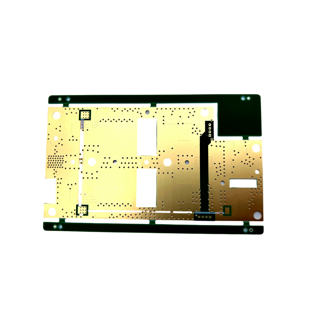
Material Selection
Material fit is more than brand selection
Rogers, PTFE, Taconic, and other low-loss laminates should be reviewed against signal target, thermal demand, resin behavior, drilling treatment, and actual build practicality.
Hybrid Stack-Up
Mixed-material builds carry hidden production risk
Rogers + FR-4 or PTFE + FR-4 structures can fail quietly at the planning stage when dielectric balance, lamination flow, and copper structure are not reviewed together.
Impedance Control
Target impedance alone does not guarantee consistency
Final impedance behavior is influenced by layer structure, dielectric thickness, copper profile, etching allowance, and fabrication tolerance across the actual build.
Prototype Risk
Late review leads to avoidable re-spin and delay
When technical review begins after quotation rather than before it, teams lose time in clarification, revision, and prototype correction that could have been filtered earlier.
Why Choose Rich FULL Joy
Rich FULL Joy focuses on engineering-driven electronics manufacturing, providing reliable PCB and PCBA solutions for high-frequency, high-speed and complex electronic systems.
High-Frequency PCB Technology
- RF and microwave PCBs
- High-speed digital PCBs
- HDI & Multilayer up to 128 layers
- Hybrid RF stack-ups
- Precision impedance control
- Laser microvia & back-drilling
Applications Across High-Tech Industries
- Satellite communication
- 5G and telecom infrastructure
- Automotive radar systems
- Aerospace electronics
- Industrial and AI hardware
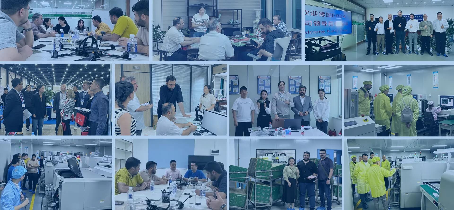
One-Stop Manufacturing
PCB fabrication, assembly, testing, and system integration.
- Component sourcing
- PCBA & functional test
Global Supply Chain
Stable component sourcing with authenticity verification.
- BOM optimization
- Short procurement cycles
Engineering Support
DFM, stack-up, signal integrity, risk assessment.
- Design optimization
- Manufacturing risk analysis
Quality & Reliability
AS9100D / ISO9001 / IATF16949, IPC Class 3.
- AOI, X-Ray, ICT, FCT
- Full traceability
More Relevant Material Capability
Rogers, PTFE, Taconic, advanced digital — matched with manufacturable stack-ups.
Stronger Hybrid Stack-Up Execution
RF + FR‑4 / high‑speed digital hybrid planning to reduce build risk.
Engineering Review Before Quote
Evaluation of material fit, stack‑up direction, via feasibility, impedance — identify risk earlier.
Beyond Prototype Support
Prototype, low‑volume, production‑intent — long‑term supplier qualification.
How Rich FULL Joy Improves Results
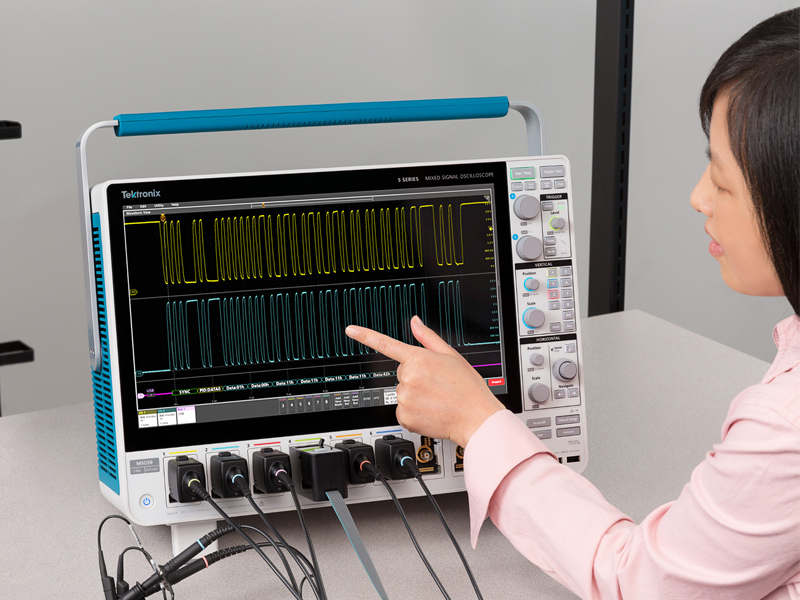
Lower Signal Loss
Dielectric selection, smoother copper, impedance‑aware routing for mmWave.
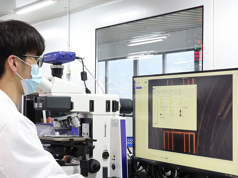
Stable Lamination
Disciplined temperature/pressure control — no voids, consistent performance.

Reliable Impedance Control
Microstrip, stripline, differential — reduce reflection, protect signal.
We Don't Just Quote.
We Engineer.
Quotation starts with engineering review
Real Risk Reduction
RF & High-Speed PCB Material Capability
Advanced laminates for demanding RF, microwave, and high‑speed digital applications.
| Material Family | Typical Grades | Dk @10GHz | Frequency Range | Typical Applications |
|---|---|---|---|---|
| Rogers | RO4350B, RO4003C, RO4835, RO5880, RO3003G2, RO3010 | 3.48 / 3.38 / 3.3 / 2.2 / 3.0 / 10.2 | DC - 20GHz (RO4000), up to 77GHz (RO3000) | Base station antennas, automotive radar, satellite communications |
| Taconic | RF-35, TLX-9, TLY-5, TLY-3, CER-10 | 3.5 / 2.5 / 2.2 / 2.3 / 10.0 | DC - 40GHz | Microwave circuits, power amplifiers, phased arrays |
| PTFE | RT/duroid 5880, 5870, Taconic TLY/TLX | 2.2 / 2.33 | up to 100GHz+ | Millimeter-wave, satellite communication, aerospace |
| High-Speed Digital | Megtron 6/7, Astra MT77, I-Speed, N4000-13SI | 3.7 / 3.0 / 3.4 / 3.8 | DC - 30GHz+ | High-speed backplanes, AI hardware, data centers |
Our Production Capabilities
Our capability of producing high-quality boards makes us the industry’s trusted RF PCB manufacturer.
| Parameter | Capability | Parameter | Capability |
|---|---|---|---|
| Number of layers | Up to 128 | Hybrid stack-ups | PTFE and non-PTFE combinations |
| Sequential lamination | Up to 4 cycles | Min trace/space | 2 mil |
| Controlled impedance | ±5% (early engagement) | Aspect ratio (microvias) | 0.75:1 |
| Aspect ratio (through-holes) | 20:1 | Hole treatment | Plasma & sodium etch |
| Metallization | Electrolysis copper | Min hole (mechanical) | 5 mil |
| Min hole (laser) | 3.5 mil | Back drill | 12 mil min, ±1 mil depth |
| Laser routing tolerance | +0.5 mil | Mech routing tolerance | ±3 mil |
| Gold plating | Selective/full, up to 120µ | Surface finishes | ENIG, Imm Tin, ENEPIG |
| Special features | Mechanical Blind Via PCB,Gold Finger PCB,HF PCB / RF PCB,RFV PCB,CI PCB,Blind Slot PCB,Back-Drilled PCB,Half-Hole PCB,Countersunk Hole PCB,Plated Blind Slot PCB,Controlled Depth Drilled PCB,HDI PCB |
These are Rich FULL Joy’s standard capabilities. If your requirements are beyond these standards, talk to our manufacturing experts at +86-188 2371 8586 and share your design requirements.
Representative Application Directions
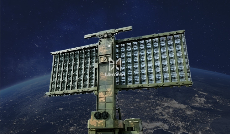
Phased-Array Radar
Rogers + FR‑4 hybrid, low‑loss RF, precision impedance.
RO4350B / FR‑4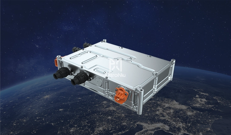
5G Base Station
Taconic material, impedance-controlled, multilayer.
Taconic RF‑35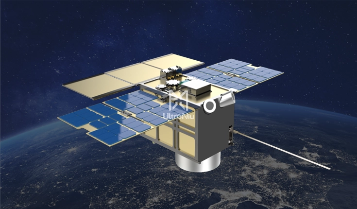
Satellite Communication
PTFE microwave stack-ups, stable lamination.
RT/duroid 5880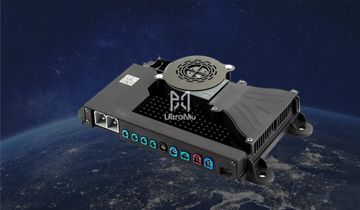
Automotive mmWave Radar
77 GHz, compact multilayer, precise impedance.
RO3003G2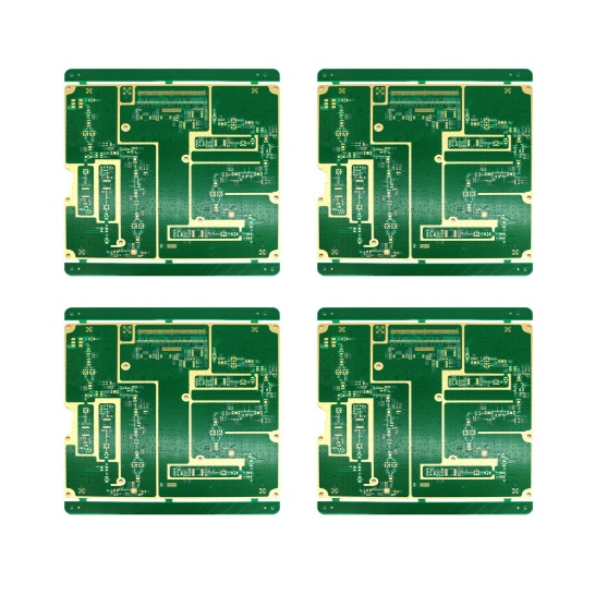
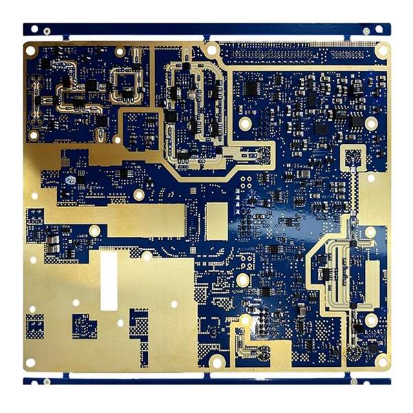
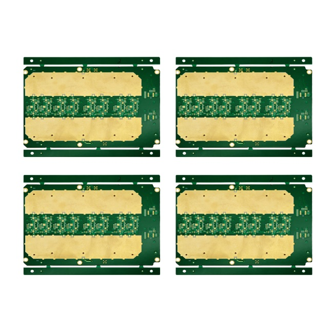
Typical Project Types

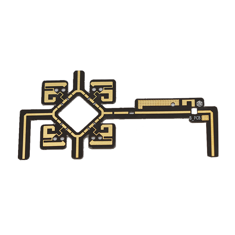


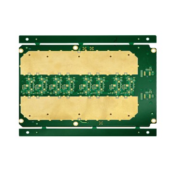
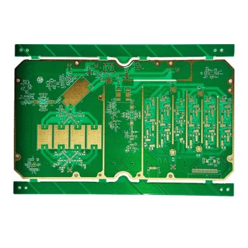
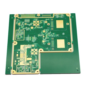
-

1.Send Files or Notes
Gerber, stack-up direction, laminate preference, impedance target, quantity, and delivery expectations are enough to begin.1 -

2.Engineering Review
Material direction, stack-up feasibility, via structure, and manufacturing risk are reviewed before the quote is treated as final.2 -

3.Technical Alignment
Laminate approach, hybrid structure, copper arrangement, and build assumptions are aligned for clearer execution.3 -

4.Quote & Lead-Time
You receive a cleaner pricing basis and clearer timing direction based on reviewed inputs.4 -

5.Prototype to Production
After prototype validation, the program can continue into pilot runs and repeat manufacturing support.5







Frequently Asked Questions
Can you support Rogers + FR-4 hybrid fabrication?
Do you offer controlled impedance for RF projects?
What files are needed for a quote?
Can you quote before design is finalized?
Do you handle prototype and small-batch production?
📘 RF Stack-Up Design Guide
Download our free guide to hybrid stack-up planning and impedance control.
Request a Quote for your high-frequency PCB project
·Stack-up direction
·Via and structure feasibility
·Impedance-related build assumptions
·Prototype and production path