Leave Your Message
-
E-mail
-
Whatsapp
-
Message
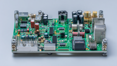
In today’s fast-moving electric vehicle scene, fine-tuning the design of On-Board Charger PCBs (OBC PCBs) is more important than ever if we really want to boost performance and efficiency. With the global EV market expected to hit around 27 million units by 2030 and a value soaring over $800 billion, having innovative and reliable OBC PCB solutions is pretty much a must.
 At Shenzhen Rich Full Joy Electronics, we're proud to be a high-tech enterprise leading the charge here in China. By blending cutting-edge engineering techniques and top-quality materials, we're aiming to dramatically improve how OBC PCBs handle heat, pack more punch into less space, and stay reliably durable. All of this helps push the EV industry toward a more sustainable future.
We’re committed to pushing boundaries and setting new standards in OBC PCB design — ultimately helping electric vehicles charge faster, better, and more efficiently. It’s an exciting time, and we’re just getting started!
At Shenzhen Rich Full Joy Electronics, we're proud to be a high-tech enterprise leading the charge here in China. By blending cutting-edge engineering techniques and top-quality materials, we're aiming to dramatically improve how OBC PCBs handle heat, pack more punch into less space, and stay reliably durable. All of this helps push the EV industry toward a more sustainable future.
We’re committed to pushing boundaries and setting new standards in OBC PCB design — ultimately helping electric vehicles charge faster, better, and more efficiently. It’s an exciting time, and we’re just getting started!
When you're designing an on-board charger (OBC) PCB, choosing the right material really matters if you want everything to run smoothly and efficiently. Ever since high-density interconnect (HDI) technology popped up, it’s become a game-changer — letting us make circuitry much smaller without sacrificing performance. That’s especially important these days, with more and more embedded systems coming into play. We need circuits that don’t take up too much space but still pack a punch in functions. Picking the right PCB material can make a huge difference when it comes to heat management, electrical performance, and reliability — all pretty critical when space is tight and efficiency is everything.
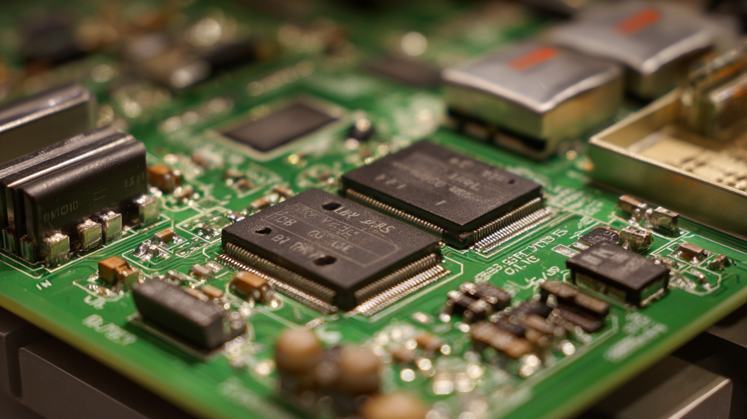
In today’s manufacturing world, especially with fancy mobile robots and automation, PCB designs have to keep pace with these growing needs. Think about wireless charging for robots — it has to be super reliable, and that’s where the right materials really shine. High-quality substrates help energy transfer happen more efficiently and boost charging performance overall. This stuff isn’t just for robots — it’s key for the future of electric vehicles and automated systems too. So, by paying attention to these details, designers can make sure their on-board chargers don’t just meet today’s standards but are also ready for whatever the future throws at us. That way, they stay competitive and future-proofed, no matter what.
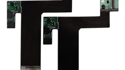
The demand for high-performance flexible printed circuit boards (FPCBs) has surged in recent years, driven by advancements in consumer electronics, automotive technology, and medical devices. According to a report by Markets and Markets, the flexible printed circuit board market is projected to grow from $23.1 billion in 2020 to $38.0 billion by 2025, reflecting a robust compound annual growth rate (CAGR) of 10.5%. This growth underscores the critical role that innovative applications and benefits of advanced 8-layer to 16-layer FPCB assembly solutions play in modern electronics.
Richfulljoy, a leading flexible PCB manufacturer since 2003, specializes in delivering custom FPCB solutions tailored to diverse applications. Our state-of-the-art 8-16 layer FPCBs are engineered with precision features, including 0.05mm laser drilling for intricate designs, and 5/5µm copper plating with less than 5% impedance variance. This level of accuracy is essential for high-density applications in foldable smartphones, surgical robotics, and electric vehicle (EV) battery modules, where reliability and performance are paramount. The thermal endurance of our polyimide-based circuits, ranging from -60°C to 180°C, further enhances their suitability across varying environments.
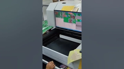
Additionally, our commitment to quality assurance is evident in our 100% Automated Optical Inspection (AOI) and In-Circuit Testing (ICT) processes, ensuring adherence to IPC Class 3 standards. Richfulljoy provides free Design for Manufacturability (DFM) analysis within six hours, facilitating efficient project development and optimization. By leveraging these innovative FPCB assembly solutions, businesses can achieve greater flexibility, durability, and performance in their electronic designs.
: The right PCB material is crucial as it influences thermal management, electrical performance, and overall reliability, which are essential for optimizing performance and efficiency in on-board chargers.
HDI technology enables significant miniaturization of circuitry, which is increasingly important as demand for compact and functional embedded systems rises.
Strategically placing components can optimize current flow, minimize power losses, and improve thermal characteristics, leading to a more efficient and stable charging process.
A star grounding layout is where all ground connections converge at a single point, which helps reduce ground loops and improves the noise performance of the charger.
Effective strategies include positioning heat-sensitive components away from heat sources, using thermal vias, dedicated heat sinks, and spacing components adequately to enhance thermal performance.
Recommended testing methods include using thermal imaging, oscilloscopes, and power analyzers to evaluate efficiency and thermal characteristics, ensuring robust PCB design.
Thermal imaging helps identify hotspots that could cause premature failure, allowing engineers to refine the layout and improve thermal management in the PCB design.
Load testing assesses voltage stability and current handling capabilities under real-world conditions, guiding design improvements to ensure compliance with performance regulations.
Incorporating feedback from various tests allows engineers to iterate on their designs, ensuring the final product meets performance expectations and regulatory standards.
Optimized PCBs can achieve performance efficiencies exceeding 96%, indicating the importance of effective design and testing in charger performance.
In today’s fast-changing world of electronics, fine-tuning your On-Board Charger PCB (OBC PCB) is pretty much essential if you want better performance and efficiency. First off, picking the right PCB material really sets the stage — it has a big say in how well heat gets managed and how reliable everything is. You also gotta think about how to handle heat effectively; that means designing your layout to spread out the heat and placing components smartly so current flows smoothly, which helps cut down on resistive losses.
On top of that, using advanced filtering techniques is a must if you want to keep signals clean, which is super important for the charger’s overall performance. Don’t forget, thorough testing and validation are key to making sure everything works just as it should. Leveraging modern design software can also make the process smoother and help improve charge efficiency — it’s like having a turbo boost for your design workflow. At Shenzhen Rich Full Joy Electronics Co., Ltd., we pride ourselves on our innovative approach, making sure we meet the highest standards in OBC PCB design, pushing the boundaries in electric vehicle charging tech.