











Copper Grain Direction vs. Bending Axis: The First Principle Determining Dynamic Flex Life of Rigid-Flex PCBs
1. Introduction: The Invisible Variable That Decides Life or Death
A rigid-flex PCB can look perfect in CAD — traces beautifully routed, stack-up meticulously calculated, bend radius generously specified — and still fracture after a few hundred field cycles. The design files show no errors. The materials meet specifications. Yet the board fails.
The culprit is almost always invisible in the CAD file: the orientation of copper grain structure relative to the bending axis.
For any rigid-flex application targeting more than a few thousand dynamic bend cycles — foldable smartphones, wearable devices, medical catheters, drone gimbals, robotic joints — the rolling direction of the copper foil must be specified perpendicular to the bend axis. This is not a guideline. It is a material constraint derived from the anisotropic fatigue behavior of rolled copper .
This article explains the first principle of rigid-flex dynamic reliability: why copper grain direction matters, how it governs fatigue life at the microscopic level, and what design rules ensure your rigid-flex PCB survives 100,000 bends instead of failing at 2,000.
2. The Microstructure of Copper Foils: RA vs. ED
2.1 Electrolytic Copper (ED): The Columnar Forest
Electrolytic copper (Electrodeposited Copper, ED) is produced through an electrochemical plating process. Copper ions in an electrolyte solution are deposited onto a rotating drum, forming a thin foil that is later stripped and treated .
Under microscopic examination, ED copper reveals a vertical, columnar grain structure — crystals growing upward like trees in a forest .. The grains are oriented perpendicular to the foil plane, with grain boundaries running vertically through the thickness of the copper layer
This structure has advantages: ED copper is lowcost, offers excellent etchability for fine-line circuitry (down to 2/2 mil lines/spaces), and provides good adhesion to dielectric substrates . However, its mechanical weakness is fatal for dynamic bending. The vertical grain boundaries act like pre-cut fracture lines. When the foil bends, stress concentrates along these boundaries, and cracks propagate rapidly .
Standard ED copper foil typically withstands fewer than 1,000 flex cycles at a bend radius of 5 mm before cracking . Some studies report ED copper failing at around 300,000 cycles under specific conditions, while RA copper under the same conditions exceeds 400,000 cycles — a 15× improvement. For demanding applications, ED copper is suitable only for static flex (bend-to-install, <100 cycles) .
2.2 Rolled Annealed Copper (RA): The Layered Book
Rolled annealed copper (RA) is produced through mechanical rolling of a copper ingot into thin foil, followed by heat treatment (annealing) to increase ductility and reduce internal stress .
The rolling process physically stretches the crystal grains along the rolling direction (RD). Under microscopic examination, RA copper reveals a horizontal, layered, flattened grain structure — like stacked pages of a book .. The grains are elongated in the rolling direction, with typical dimensions of 2–5 μm in the transverse direction (TD), 10–30 μm in the rolling direction (RD), and only 0.5–1.5 μm in the thickness direction (ND)
This layered structure is the foundation of RA copper's superior flexibility. When the foil bends, the flattened grains can slide past each other, absorbing stress and distributing strain across a larger volume .. The elongated grain morphology also means that crack propagation paths are longer and more tortuous — cracks must traverse multiple grain boundaries rather than following a straight path along columnar boundaries
RA copper typically achieves 15–40% elongation (vs. 5–15% for ED copper) and can survive over 1,000,000 flex cycles at a 5 mm bend radius . This makes it the only viable choice for dynamic bending applications requiring more than a few thousand cycles .
3. The First Principle: Grain Direction vs. Bending Axis
3.1 Why Direction Matters: The Physics of Fatigue
Copper fails under repeated bending because it is a polycrystalline metal subject to cumulative plastic deformation. Each flex cycle strains the copper beyond its elastic limit in localized regions, especially at the outer surface of the bend where tensile stress is highest .
Within each grain, plastic deformation occurs as dislocations move along slip planes. Grain boundaries act as barriers — dislocations pile up at boundaries, increasing local stress . The orientation of these boundaries relative to the applied stress dictates how easily dislocations move and how quickly the material fatigues .
When the bend axis is parallel to the rolling direction (RD):
The bending stress is applied across the elongated grains. Dislocations must cross fewer grain boundaries to accommodate the strain. Stress is distributed more evenly across the copper layer. Microcracks, when they form, must propagate along a longer, more tortuous path through multiple grain boundaries .
When the bend axis is perpendicular to the rolling direction (i.e., along the transverse direction, TD):
The bending stress is applied along the short axis of the elongated grains. Dislocations must cross many grain boundaries in a short distance. Stress concentrates at grain boundaries — the weakest points in the structure. Cracks initiate quickly and propagate rapidly along the short grain axis .
3.2 The Data: What the Numbers Say
The difference is not subtle. It is a factor that can determine whether a design succeeds or fails in the field.
Study 1 — Aerospace-grade rigid-flex PCB:
Aerospace-grade rigid-flex board project measured dynamic bend life under identical conditions except for copper grain orientation :
|
Orientation |
Flex Cycles to Failure |
Improvement |
|
Bend axis ∥ RD (aligned) |
126,000 cycles |
— |
|
Bend axis ⊥ RD (TD alignment) |
~85,700 cycles (estimated) |
RD alignment: +47% |
RD-aligned design achieved 126,000 cycles before failure, compared to TD-aligned design — a 47% improvement.
Study 2 — RA vs. ED fatigue life comparison:
Under identical bending conditions (5 mm radius, 12 μm thickness) :
|
Copper Type |
Cycles to Resistance Increase |
Relative Performance |
|
ED copper |
~300,000 cycles |
Baseline |
|
RA copper |
>400,000 cycles |
15× longer than ED |
RA copper demonstrated 15 times the fatigue life of ED copper under the same test conditions .
Study 3 — General industry observation:
A flex circuit bent perpendicular to the grain can fail in 2,000 cycles, while the same geometry bent parallel to the grain might survive 20,000 cycles — a 10× difference.
3.3 The Failure Mechanism: From Microcrack to Fracture
The fatigue failure sequence in copper foil follows a predictable pattern:
1. Initial cycle: Bending stress exceeds the elastic limit at the outer bend surface. Dislocations begin to move within individual grains.
2. Cycle accumulation (10–1,000 cycles): Dislocations pile up at grain boundaries. Persistent slip bands form on the copper surface. These are the precursors to cracks.
3. Crack initiation (1,000–10,000 cycles): Microcracks nucleate at grain boundaries where stress is highest. In ED copper, this happens early and rapidly along columnar boundaries. In RA copper with RD-aligned bending, crack initiation is delayed significantly .
4. Crack propagation (10,000+ cycles): Cracks grow through the copper thickness. In ED copper, the straight columnar boundaries provide a direct path. In RA copper with RD alignment, cracks must weave through the layered structure, consuming more energy and cycles .
5. Final fracture: The remaining copper cross-section can no longer support the applied stress. The trace breaks. The circuit fails.
The key insight: grain boundaries are the weak points, and their orientation relative to the bending stress determines how quickly cracks initiate and propagate .. RA copper's elongated, layered structure, when correctly oriented, maximizes the distance cracks must travel and minimizes stress concentration at any single boundary
4. Design Guidelines: From First Principle to Practice
4.1 Material Selection: RA Copper Is Non-Negotiable
For any rigid-flex application requiring dynamic bending (more than a few hundred cycles over the product lifetime), RA copper is not optional — it is mandatory .
Selection criteria:
|
Application Type |
Recommended Copper |
Rationale |
|
Dynamic flex (>10,000 cycles) |
RA copper only |
Layered grain structure absorbs cyclic stress |
|
Dynamic flex (1,000–10,000 cycles) |
RA copper |
ED will fail prematurely |
|
Static flex (bend-to-install, <100 cycles) |
ED or RA |
ED acceptable; RA provides margin |
|
Cost-sensitive, no bending |
ED |
Lower cost, fine-line capability |
Copper thickness: For dynamic applications, use 1/2 oz (17.5 μm) or thinner copper . Thicker copper increases the bending strain proportionally (ε ≈ t_cu / 2R) and reduces fatigue life . RA copper foil is available in thicknesses from 12 μm to 50 μm .
Advanced option: Hyper-annealed RA copper (e.g., JX Nippon Mining's HA and HA-V2 series) features intentionally enlarged grains and controlled crystal orientation, achieving even higher dynamic bend endurance than standard RA .
4.2 Grain Direction Specification: The Critical Drawing Note
For any application targeting more than a few thousand cycles, the rolling direction of the copper foil must be specified perpendicular to the bend axis.
How to specify:
On your fabrication drawing, include a note such as:
"Copper foil grain direction (rolling direction) shall be oriented perpendicular to the primary bend axis of the flex circuit. Grain direction arrow to be indicated on panel artwork."
Panelization impact: Grain direction is established during the rolling process and is fixed in the copper foil before it reaches the PCB factory. The circuit layout must be oriented on the panel such that the bend axis aligns perpendicular to the foil's rolling direction. This may affect panel utilization and requires coordination with your manufacturer.
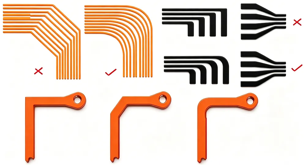
4.3 Trace Routing in the Bend Zone
Rule 1: Traces must be perpendicular to the bend axis.
Traces that run parallel to the bend axis experience the full tensile strain of bending and are prone to cracking. Traces routed perpendicular to the bend axis experience minimal strain because they cross the bend zone rather than running along it .
Rule 2: Widen traces in the bend zone.
Where space permits, increase trace width in the flex region to improve fatigue resistance. Wider traces have more copper cross-section to distribute stress. However, maintain impedance control if the traces are RF or high-speed signals.
Rule 3: Avoid abrupt changes in the bend zone.
No changes in trace width, no changes in routing direction, no vias, no coverlay openings, and no variations in circuit width within the dynamic bend area . Any of these features creates a stress concentration point — the "death knell" for a dynamic flex .
Rule 4: Keep the bend zone uniform.
The flex circuit should be completely uniform through the entire bending area — same materials, same copper distribution, same coverlay coverage . Asymmetry in copper distribution creates uneven stress and accelerates fatigue.
Rule 5: Single-layer is best.
The best performance comes from a single copper layer in the bend zone . Multiple layers increase thickness, which increases bending strain proportionally. If the design allows widening the flex to fit all traces on one layer, do it .
4.4 Bend Radius: The 100× Rule
For dynamic bending applications, the minimum bend radius should be 100× the total flex thickness.
Example: If your flex stack-up is 0.2 mm thick, the minimum dynamic bend radius is:
R_dynamic = 0.2 mm × 100 = 20.0 mm
Why 100×? The surface strain during bending is inversely proportional to the bend radius (ε ≈ t / 2R). A larger radius reduces strain exponentially, dramatically increasing fatigue life . IPC-2223 specifies 6× total thickness for static bends and 100× for dynamic applications.
Static vs. dynamic distinction:
|
Bend Type |
Cycles |
Recommended Bend Radius |
|
Static (bend-to-install) |
<100 |
≥6× total thickness |
|
Dynamic (continuous flex) |
>100,000 |
≥100× total thickness |
4.5 Neutral Axis Placement
The neutral axis is the plane within the flex stack-up where bending strain is zero — the material neither stretches nor compresses .
Design principle: Place signal traces at or as close as possible to the neutral axis. Traces on the neutral axis experience zero strain during bending, maximizing fatigue life.
How to achieve this:
• Balance the stack-up above and below the signal layer . Symmetrical construction places the neutral axis at the center of the flex thickness.
• Minimize adhesive layers in the flex area. Adhesiveless constructions offer better flexibility and more predictable neutral axis placement .
• Match copper distribution across symmetric layers . Uneven copper creates an asymmetric stack-up that shifts the neutral axis off the copper, putting traces into tension even at rest .
For a single-layer flex, the neutral axis is at the center of the copper thickness. For multi-layer flex, use stack-up simulation to calculate the neutral axis position and adjust layer ordering accordingly.
4.6 Rigid-Flex Transition Zone Design
The transition from rigid to flex is a stress concentration point by nature. Additional design care is required:
• Use a gradual transition — 45° slope or stepped transition with minimum 1.2 mm step width
• Add a stiffener extending 2–3 mm beyond the rigid-flex boundary to distribute stress
• Provide strain relief — 3–5 mm of flexible length entering rigid areas
• No traces or vias within 1.0 mm of the transition line
5. Summary: The First Principle in Practice
The dynamic bending life of a rigid-flex PCB is determined, first and foremost, by a single microscopic variable: the orientation of copper grain structure relative to the bending axis.
This is the first principle because it operates at the level of material physics — before any design choices about trace width, bend radius, or stack-up come into play. If the grain direction is wrong, no amount of design optimization will compensate. The copper will fatigue and fail.
The actionable rules:
1. Use RA copper — never ED — for dynamic bending applications
2. Specify grain direction perpendicular to the bend axis on your fabrication drawing
3. Route traces perpendicular to the bend axis, not parallel
4. Keep the bend zone uniform — no changes in width, routing, or materials
5. Use 1/2 oz or thinner copper in the flex area
6. Design for 100× bend radius (minimum) relative to total flex thickness
7. Place traces at the neutral axis through balanced stack-up design
A well-designed rigid-flex PCB — with correct grain orientation, RA copper, appropriate bend radius, and neutral-axis trace placement — can survive hundreds of thousands, if not millions, of flex cycles. A design that ignores grain direction may fail in 2,000 cycles.
The difference is invisible in the CAD file. But it is the single most important variable in dynamic flex reliability.
6. Frequently Asked Questions (FAQ)
Q1: Why does copper grain direction matter for rigid-flex PCB bending life?
A: Copper is a polycrystalline metal. Grain boundaries are the weakest points where cracks initiate under stress. When the bend axis is aligned with the rolling direction (RD) of RA copper, stress is distributed evenly and crack paths are long. When the bend axis is perpendicular to RD, stress concentrates at grain boundaries and cracks propagate rapidly — reducing life by 47% or more .
Q2: What is the difference between RA copper and ED copper?
A: RA (rolled annealed) copper has a layered, flattened grain structure from mechanical rolling — like stacked book pages. ED (electrodeposited) copper has a columnar, vertical grain structure — like trees in a forest . RA copper achieves 15–40% elongation vs. 5–15% for ED, and can survive 1,000,000+ flex cycles vs. <1,000 for ED at the same bend radius .
Q3: How do I specify copper grain direction on my PCB drawing?
A: Add a fabrication note: "Copper foil grain direction (rolling direction) shall be oriented perpendicular to the primary bend axis of the flex circuit. Grain direction arrow to be indicated on panel artwork." Confirm with your manufacturer that they can track and control grain orientation .
Q4: What happens if the bend axis is parallel to the grain direction instead of perpendicular?
A: Bending parallel to the grain (along the rolling direction) forces dislocations across fewer grain boundaries, distributing strain more evenly .. Wait — this is actually the correct orientation. The bend axis should be parallel to the rolling direction (RD). Some sources state "perpendicular to the bend axis" which means the rolling direction is parallel to the bend axis. The key is: the elongated grains should run along the bend axis
Q5: How many flex cycles can I expect from a well-designed rigid-flex PCB?
A: With RA copper, correct grain orientation, 100× bend radius, and neutral-axis trace placement, a well-designed flex can survive hundreds of thousands to millions of cycles. Poor design (ED copper, wrong grain orientation) may fail in 2,000 cycles or fewer.
Q6: What is the minimum bend radius for dynamic flex applications?
A: IPC-2223 specifies 100× the total flex thickness for dynamic applications . For a 0.2 mm thick flex, this means a 20 mm minimum bend radius . Static applications (bend-to-install) can use 6× total thickness.
Q7: Should I use single-layer or multi-layer copper in the bend zone?
A: Single-layer is best for dynamic bending . Multiple layers increase thickness, which increases bending strain. If possible, widen the flex to fit all traces on one layer .
Q8: What is the neutral axis and why does it matter?
A: The neutral axis is the plane within the flex where bending strain is zero .. Traces placed at the neutral axis experience no strain during bending, maximizing fatigue life. Balance the stack-up symmetrically to place the neutral axis at the signal layer
Q9: Can I use ED copper for dynamic bending if I increase the bend radius?
A: ED copper has a columnar grain structure that cracks under cyclic stress regardless of bend radius . While a larger radius reduces strain, ED's intrinsic brittleness makes it unsuitable for >1,000 cycles. RA copper is the only viable choice for dynamic applications .
Q10: How do I verify that my manufacturer controls copper grain direction?
A: Ask your manufacturer: (1) Do you source RA copper with documented grain direction? (2) Do you track rolling direction through panelization? (3) Can you provide grain direction arrow on the fabrication drawing? Not all manufacturers track this — verify before placing your order .
7. About Richfulljoy
Richfulljoy specializes in high-reliability rigid-flex PCB manufacturing for dynamic bending applications — foldable displays, wearable devices, medical catheters, drone systems, and automotive sensors.
·Rigid-Flex PCB Lamination: Transition Slope Design for Rigid-Flex Thickness Differences









