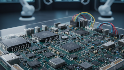
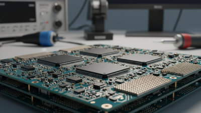
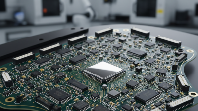
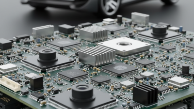
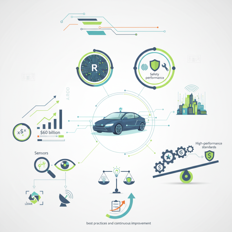
Choosing the right PCB for autonomous driving sensors is such a big deal when it comes to making vehicles safer and more efficient. As more and more folks jump into the self-driving car scene, experts are saying the market could hit around $60 billion by 2030 — and sensors are really at the heart of this boom. A good, solid PCB isn’t just about keeping things running; it’s what makes sure the sensors can do their job properly — like sensing your surroundings accurately and helping the car make the right decisions.
As Dr. Elaine Jenkins from Tech Innovations Inc. puts it, "Reliability is everything when designing PCBs for autonomous driving sensors." She points out how tricky it can be to manufacture these specialized boards. You’ve got all these sensors—LIDAR, radar, you name it—that need to work together seamlessly. Each one has its own needs when it comes to materials and setup, so choosing the right PCB becomes a pretty big deal.
On top of that, companies are always trying to strike a balance between keeping costs down and making sure everything performs like it should. It’s no surprise that some manufacturers may cut corners here and there, but that can seriously affect the quality of these PCBs. Finding that sweet spot between innovation, quality, and affordability is key. In this competitive game, staying up-to-date with best practices and always aiming to improve your PCB design is what’s gonna keep you ahead. It’s all about thinking long-term and making sure your tech works reliably over time.
Understanding the Role of PCBs in Autonomous Driving Sensors
PCBs play a critical role in autonomous driving sensors. These sensors rely on PCBs to process data in real time. Precision is essential. A recent industry report shows that over 60% of sensor errors can be traced back to PCB design flaws. This statistic highlights the importance of careful selection.
When choosing PCBs for autonomous vehicles, several factors must be considered. First, material quality is crucial. High-quality materials reduce overheating risks. Thermal management is vital in ensuring sensor reliability. Additionally, the layout design impacts signal integrity. Poor layouts can lead to interference, causing malfunction.
Design teams must also pay attention to component placement. The proximity of components can affect performance. According to a market analysis, 30% of performance issues stem from inadequate spacing. This is a significant percentage. It emphasizes the need for thorough analysis and iterative refinements in designs. Ultimately, choosing the right Pcb For Autonomous Vehicles is complex. It requires attention to detail and a willingness to reflect on past design pitfalls.
Key Considerations for PCB Material Selection in Autonomous Applications
When selecting PCB materials for autonomous driving sensors, several factors play a critical role. Heat dissipation is essential, as many sensor components generate significant heat. High-temperature materials like polyimide are often preferred, handling extreme environments. According to industry reports, nearly 30% of sensor failures relate to thermal issues. Thus, choosing the right substrate is crucial to ensure reliability.
Another consideration is the flexibility of the PCB. The design of autonomous vehicles requires intricate shapes and sizes. Materials like FR-4 offer decent flexibility but may not suffice for all applications. Some reports indicate that nearly 20% of PCBs in autonomous vehicles now utilize flexible materials. This choice allows for innovative designs that fit compact spaces, which is a growing trend.
Frequency response is also vital. Autonomous sensors operate in varied frequency ranges, demanding materials that ensure optimal signal integrity. A poor choice can lead to compromised data quality. Interestingly, it has been observed that up to 25% of PCB issues are related to improper material selection. The demand for ODM PCBA Solutions for Autonomous Vehicles highlights the need for advanced materials tailored for challenging applications.
Evaluating Layer Count and Stack-Up Design for Sensor PCBs
When designing PCBs for autonomous driving sensors, layer count and stack-up design are critical factors. A recent report indicates that PCBs with four to eight layers are common for sensor applications. The increased layer count allows for more complex circuits and better signal integrity. This is particularly important for high-frequency sensors used in LiDAR and radar systems. However, more layers mean higher costs and longer production times. It's essential to balance performance and cost.
The stack-up design also impacts electromagnetic interference (EMI) and thermal management. Placing power and ground layers strategically can minimize noise and improve signal quality. For instance, one study found that a well-designed stack-up can reduce EMI by up to 30%. However, achieving this requires careful consideration of the material properties and the application's specific demands. Many designers often overlook these details, focusing solely on the sensor's core functionality.
While optimizing layer count and stack-up is vital, challenges remain. The complexity of modern sensors necessitates innovative solutions. Continuous advancements in materials and manufacturing techniques are essential. Designers must remain flexible, adapting to the rapidly evolving sensor technologies. Mistakes in layer design can lead to significant performance issues, necessitating reflectiveness in design choices.
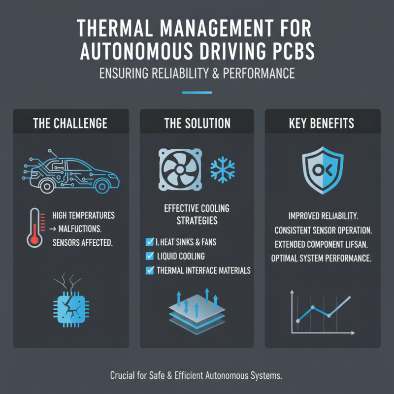
Thermal Management Strategies for PCBs in Autonomous Driving Systems
Thermal management is crucial for PCBs in autonomous driving systems. High temperatures can cause malfunctions. Sensors must operate effectively in varying conditions. Effective cooling solutions help maintain performance.
One common strategy involves heat sinks. They dissipate heat away from critical components. However, designing these can be challenging. Placement and size matter greatly. If designed poorly, they might not work as intended.
Another approach is the use of thermal pads. These fill gaps between components and the PCB. They can improve heat transfer, yet their material choice must be precise. An unsuitable pad can trap heat instead of dispersing it. Overall, continuous testing and adjustments are necessary for efficiency.
Designing for Signal Integrity in High-Frequency Sensor PCBs
Designing high-frequency sensor PCBs requires a keen focus on signal integrity. In autonomous driving, low latency is crucial. The PCB's layout significantly influences performance. A report by the IEEE notes that nearly 56% of design errors stem from poor signal quality. Engineers must prioritize minimizing trace length and avoiding sharp turns. Each bend can introduce unwanted inductance, harming signal transmission.
Incorporating differential pairs greatly enhances the PCB's resilience to noise. Data from PCB Tech Research highlights that differential signaling can reduce electromagnetic interference by up to 27%. High-frequency sensors like those found in Vishay Sensors applications rely on stable signals. Designers should consider using controlled impedance constructions to maintain signal integrity.
Thermal management also plays a vital role. Excess heat can cause performance issues. It's reported that up to 40% of PCBs fail in high-temperature scenarios. Employing effective heat sinks and thermal vias can mitigate these risks. Continuous testing and iteration in designs reveal hidden flaws early, thereby improving longevity and reliability. Tailoring designs for the specific sensor applications ensures stability and accuracy in demanding environments.
How to Choose PCB for Autonomous Driving Sensors? - Designing for Signal Integrity in High-Frequency Sensor PCBs
| PCB Parameter |
Recommended Value/Type |
Impact on Signal Integrity |
| Layer Count |
4-6 Layers |
Allows better routing for high-frequency signals. |
| Material Type |
FR-4 or Rogers |
High dielectric constant reduces signal loss. |
| Trace Width |
0.5mm - 1.0mm |
Wider traces minimize resistance and heat. |
| Impedance Control |
50 Ohms |
Essential for high-frequency transmission. |
| Via Type |
Micro Vias |
Reduces inductance and enhances signal integrity. |
| Finish Type |
ENIG (Electroless Nickel Immersion Gold) |
Provides excellent solderability and corrosion resistance. |
| Thermal Management |
Thermal vias and copper pours |
Enhances heat dissipation from high-power components. |
Environmental Considerations for PCB Durability in Autonomous Vehicles
In the realm of autonomous vehicles, selecting the right PCB is critical for sensor durability. Environmental factors significantly impact PCBs. According to a report by the International Automotive Research, nearly 40% of PCB failures are attributed to environmental stress. Extreme temperatures, humidity, and vibrations can compromise their integrity.
High-performance sensors must endure harsh conditions. For instance, a temperature range of -40°C to 125°C is typical for automotive applications. Moreover, moisture can lead to delamination and corrosion, which affects functionality. A PCB designed for automotive use must be encapsulated or conformally coated to resist these challenges.
Vibration can also cause fatigue in PCBs. The automotive environment is rife with constant jostling, especially in urban areas. According to estimates, vibrations can vary between 5 Hz and 200 Hz, leading to structural stress. Hence, rigorous stress testing and material selection are essential. While current testing methods are robust, gaps remain.
Evaluating new materials and advanced coatings can improve resilience but requires ongoing research and development.
Testing and Validation Processes for Autonomous Driving PCB Designs
When designing PCBs for autonomous driving sensors, testing and validation are crucial. Reliable performance hinges on ensuring that the sensors function as intended in real-world conditions. One area of focus is thermal performance. It is vital to check how these boards handle temperature fluctuations. For example, using Honeywell Temperature Sensors can assist in monitoring thermal changes. These sensors offer critical data, helping engineers identify any shortcomings in heat management.
The validation process should include environmental testing. Subjecting the PCB to extreme conditions helps reveal potential failures. Vibration testing is another key aspect. It simulates real-life scenarios where the sensor might face physical stress. Occasionally, designs may not withstand these tests as expected, prompting a redesign. Engineers must remain open to iterations, striving for optimal performance.
Another consideration is the integration of components. Every piece must work seamlessly together. Any misalignment can lead to malfunction. During testing, unexpected issues may arise. This reflects the importance of a systematic approach. Thorough analysis of test results can highlight areas for improvement. Continuous learning and refinement ensure that designs meet reliability standards essential for autonomous driving.
Innovative High-Reliability Rigid-Flex PCB Solutions for Advancements in AI and Medical Device Technologies
The integration of AI and medical device technologies is not just a trend but a necessity for advancing the quality of healthcare and industrial applications. Innovative high-reliability rigid-flex PCBs play a crucial role in this evolution by offering exceptional performance and durability for applications where reliability is paramount. Recent industry reports indicate that the rigid-flex PCB market is projected to grow significantly, driven by the demand for miniaturization and enhanced device functionality in sectors such as healthcare and AI.
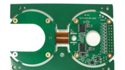
Our rigid-flex PCB solutions are engineered to meet the complex requirements of modern technologies. The multi-layer construction seamlessly combines rigid and flexible layers, allowing for greater design flexibility and space efficiency. With high-quality materials like polyimide and FR4, these PCBs support fine-pitch components and are optimized for high-frequency applications. According to a recent study, devices that incorporate such advanced PCB technology can achieve up to 30% reduced footprints while maintaining mechanical stability and performance under demanding conditions.
Moreover, these PCBs are designed with stringent industry standards in mind, including ISO 13485 for medical devices and IPC-6013 for rigid/flexible circuit boards. This ensures that our solutions not only excel in performance but also comply with the highest safety and quality benchmarks. These characteristics make our rigid-flex PCBs indispensable in applications ranging from wearable health monitoring devices to sophisticated robotic surgery systems, thereby driving forward the capabilities of both AI technologies and medical innovations.
FAQS
: PCBs process data in real time for these sensors. Their role is critical for reliability.
High-quality materials reduce overheating risks and improve thermal management, ensuring sensor reliability.
Poor layouts can lead to signal interference and malfunctions, impacting overall sensor performance.
About 30% of performance issues come from inadequate component spacing in PCB designs.
PCBs usually have four to eight layers, balancing performance with cost effectively.
A well-designed stack-up can reduce electromagnetic interference and improve signal quality significantly.
The complexity of modern sensors requires continuous adaptation and innovative solutions from designers.
Designers must learn from previous errors in spatial arrangements and layer designs for better results.
Attention to material quality, layout design, and component placement must be prioritized for optimal performance.
Yes, overlooking details like EMI and thermal management can lead to serious performance issues.
Conclusion
The article "How to Choose PCB for Autonomous Driving Sensors?" provides a comprehensive overview of the critical aspects involved in selecting PCBs for advanced autonomous driving applications. It begins by explaining the essential role that PCBs play in the functionality of driving sensors, emphasizing the importance of material selection to meet the specific demands of autonomous systems.
Furthermore, the article highlights the significance of evaluating layer count and stack-up design to ensure optimal performance of sensor PCBs. Key strategies for effective thermal management and maintaining signal integrity in high-frequency operations are discussed, alongside considerations for environmental durability to withstand the harsh conditions faced by autonomous vehicles. Lastly, the article underscores the crucial testing and validation processes required to ensure reliable PCB designs for autonomous driving sensors, ultimately guiding engineers in making informed decisions in their PCB selection process.