











ENIG vs HASL in RF Performance: Which Surface Finish Is Better for RF PCBs?
When discussing RF PCB performance, engineers often focus on dielectric materials, stackup design, impedance control, and transmission line geometry. Surface finish selection is frequently considered a manufacturing detail rather than an electrical design parameter.
However, as operating frequencies move into the microwave and millimeter-wave range, surface finish becomes increasingly important.
The final finish applied to copper conductors directly affects conductor roughness, current distribution, impedance stability, insertion loss, solder joint reliability, and long-term environmental performance. While both Electroless Nickel Immersion Gold (ENIG) and Hot Air Solder Leveling (HASL) are widely used in PCB manufacturing, their impact on RF circuits differs significantly.
In many high-frequency designs, the choice between ENIG and HASL can influence system performance as much as material selection. Engineers designing 5G infrastructure, phased-array antennas, satellite communication systems, automotive radar modules, and microwave power amplifiers must understand how surface finish characteristics affect signal propagation.
This article compares ENIG and HASL from an RF engineering perspective and explains why surface finish selection should be considered an integral part of RF PCB design.
Understanding ENIG and HASL Surface Finishes
Surface finish serves two primary functions in PCB manufacturing:
• Protecting exposed copper from oxidation
• Providing a solderable surface for component assembly
ENIG consists of:
• Electroless Nickel layer
• Thin immersion gold layer
Typical structure:
• Nickel thickness: 3–6 μm
• Gold thickness: 0.05–0.15 μm
The gold protects the nickel from oxidation, while the nickel serves as the primary barrier layer.
HASL, by contrast, applies molten solder onto exposed copper surfaces and removes excess solder using hot air knives.
Typical HASL coatings contain:
• Tin-lead solder (traditional)
• Lead-free solder alloys (modern applications)
Although both finishes achieve solderability objectives, their electrical and mechanical characteristics differ substantially.
For low-frequency products, these differences are often negligible.
For RF PCBs, they become increasingly important.
How Surface Finish Influences RF Signals
Many engineers assume RF current flows through bulk copper.
In reality, high-frequency current is concentrated near conductor surfaces because of skin effect.
As frequency increases:
• Current penetration depth decreases
• Surface characteristics become dominant
• Surface finish begins influencing conductor loss
Several factors become important.
Surface Roughness
Rougher conductor surfaces increase current path length.
This creates:
• Higher conductor loss
• Increased insertion loss
• Reduced signal efficiency
Conductivity
Different metals exhibit different conductivity values.
Conductivity affects:
• Signal attenuation
• Current distribution
• RF efficiency
Dimensional Uniformity
Surface finish can influence:
• Trace geometry
• Controlled impedance structures
• Repeatability across production lots
These effects become increasingly visible above 10GHz.
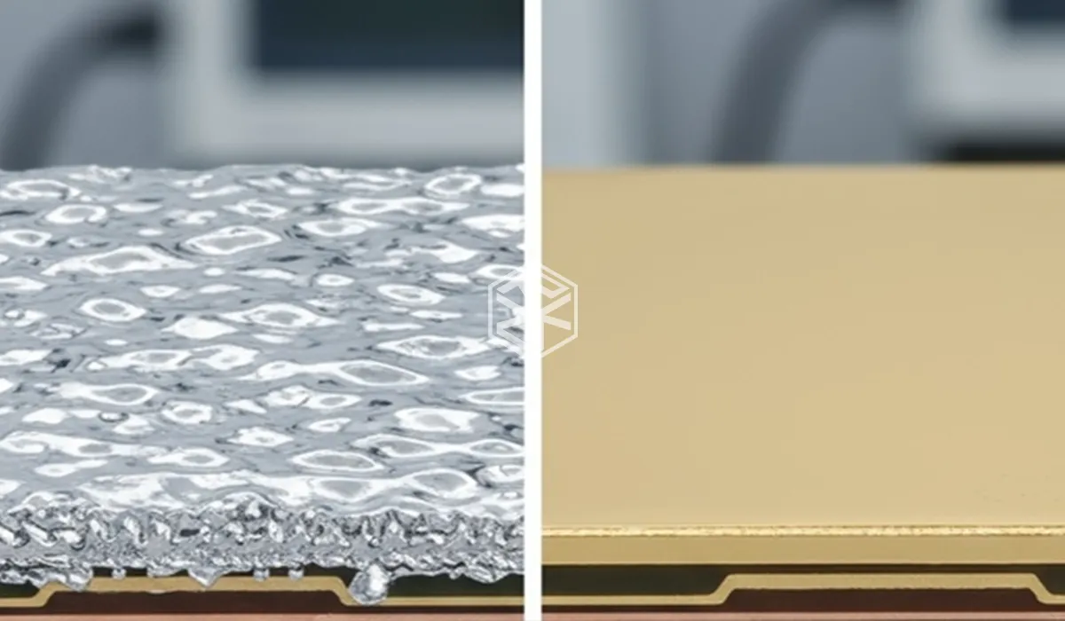
Performance Comparison: ENIG vs HASL
Surface Flatness
One of the biggest differences is planarity.
ENIG produces an extremely flat surface.
HASL creates uneven solder thickness because molten solder naturally accumulates in different areas.
For RF transmission lines, dimensional consistency is critical.
Advantage: ENIG
Impedance Control
Controlled impedance depends on precise conductor geometry.
The uneven surface created by HASL introduces dimensional variation that can affect:
• Microstrip structures
• Coplanar waveguides
• Differential RF routing
ENIG maintains much tighter dimensional control.
Advantage: ENIG
Insertion Loss
At high frequencies, insertion loss becomes highly sensitive to conductor surface characteristics.
Although ENIG introduces a nickel layer that has lower conductivity than copper, the finish remains highly consistent.
HASL introduces irregular solder profiles that create impedance variation and current path irregularities.
In most microwave applications, ENIG delivers more predictable insertion loss performance.
Advantage: ENIG
Fine-Pitch RF Components
Modern RF modules often use:
• QFN packages
• BGA packages
• Antenna-in-package technologies
ENIG provides excellent coplanarity and assembly reliability.
HASL can create solder thickness variation that affects assembly quality.
Advantage: ENIG
Cost
HASL remains one of the most economical surface finishes.
ENIG requires more process steps and higher material cost.
Advantage: HASL
Summary Comparison
| Parameter | ENIG | HASL |
|---|---|---|
| Surface Flatness | Excellent | Moderate |
| Impedance Stability | Excellent | Fair |
| High-Frequency Performance | Excellent | Moderate |
| Fine-Pitch Assembly | Excellent | Limited |
| Cost | Higher | Lower |
| Repeatability | Excellent | Moderate |
Manufacturing Considerations
From a fabrication perspective, both finishes present unique challenges.
ENIG Manufacturing
Advantages:
• Excellent surface uniformity
• Flat conductor profile
• Suitable for RF and HDI designs
• Excellent shelf life
Challenges:
• Nickel thickness control
• Black pad prevention
• Higher process cost
HASL Manufacturing
Advantages:
• Lower cost
• Mature process
• Excellent solderability
Challenges:
• Surface non-uniformity
• Thickness variation
• Not ideal for fine-line RF structures
As RF frequencies increase, manufacturing consistency becomes increasingly valuable.
This often justifies the additional cost of ENIG.
Design Considerations for RF Applications
Surface finish should be selected according to operating frequency and performance requirements.
Below 3GHz
Many commercial products can operate successfully with HASL.
Performance impact is generally limited.
3GHz to 10GHz
ENIG begins providing measurable benefits in impedance consistency and dimensional control.
Above 10GHz
Most RF designers strongly prefer ENIG.
At these frequencies:
• Small geometric variations matter
• Return loss becomes more sensitive
• Insertion loss increases rapidly
Millimeter-Wave Applications
For:
• 24GHz radar
• 39GHz communication systems
• 60GHz wireless products
• 77GHz automotive radar
ENIG is typically considered the standard choice.
The improved consistency often outweighs the higher manufacturing cost.
Real RF PCB Application Example
A customer developing a 24GHz radar module initially selected HASL to reduce manufacturing costs.
The design met all schematic and simulation requirements.
However, production testing revealed:
• Channel-to-channel variation
• Higher-than-expected insertion loss
• Reduced antenna efficiency
Investigation showed that uneven solder thickness introduced slight variations in conductor geometry across critical RF routing regions.
The design was later manufactured using ENIG.
Testing showed:
• Improved impedance consistency
• Better phase matching
• Reduced insertion loss variation
• More repeatable antenna performance
The improvement was achieved without changing the PCB layout or material system.
Only the surface finish changed.
Failure Analysis and Common Mistakes
Several RF performance problems can be traced to inappropriate surface finish selection.
Assuming Surface Finish Does Not Affect RF Performance
Many engineers focus exclusively on dielectric materials while ignoring conductor surface characteristics.
At microwave frequencies, both matter.
Selecting HASL Solely for Cost Reduction
The savings achieved through HASL may be offset by:
• Lower yield
• More tuning effort
• Increased validation costs
Ignoring Assembly Requirements
Fine-pitch RF modules often require highly planar surfaces.
HASL may introduce assembly challenges.
Applying Low-Frequency Design Rules to Microwave Systems
Design practices that work at 1GHz may not work at 24GHz or 77GHz.
Surface finish becomes increasingly important as frequency rises.
Conclusion
The comparison between ENIG and HASL is not simply a manufacturing decision—it is an RF performance decision.
For low-frequency products, HASL remains a cost-effective and reliable option. However, as operating frequencies move into microwave and millimeter-wave ranges, the limitations of HASL become increasingly apparent.
ENIG provides superior surface flatness, tighter impedance control, improved assembly performance, and greater manufacturing consistency. These characteristics make it the preferred finish for most modern RF PCB applications, including 5G infrastructure, radar systems, aerospace electronics, satellite communications, and advanced antenna designs.
While ENIG introduces additional manufacturing cost, the benefits in signal integrity, repeatability, and long-term reliability often outweigh the initial investment.
For RF engineers, the question is no longer whether surface finish matters. The question is whether the chosen finish supports the performance goals of the system.
FAQ
Is ENIG always better than HASL for RF PCBs?
For most RF applications above 10GHz, ENIG generally provides superior performance due to its flat surface and consistent geometry.
Does the nickel layer in ENIG increase RF loss?
Nickel has lower conductivity than copper, but in most practical RF designs, the benefits of surface uniformity outweigh the additional loss contribution.
Can HASL be used for RF PCBs?
Yes. HASL can perform adequately in lower-frequency RF applications, particularly below 3GHz.
Why is ENIG preferred for radar PCBs?
Radar systems require precise impedance control and phase matching. ENIG provides better dimensional consistency than HASL.
Which finish is better for 77GHz radar applications?
ENIG is generally the preferred choice because millimeter-wave systems are highly sensitive to conductor geometry variations.
Does surface finish affect insertion loss?
Yes. Surface roughness, conductivity, and dimensional consistency all influence insertion loss.
Is ENIG suitable for fine-pitch RF modules?
Yes. ENIG provides excellent coplanarity and is widely used for BGA, QFN, and advanced RF packaging technologies.
Should cost or performance drive surface finish selection?
For RF and microwave products, performance requirements should typically drive the decision, especially above 10GHz.









