











Does High-Frequency Board Need Gold Finger Processing?
1. Introduction: The Core Question
The question of whether high-frequency printed circuit boards require gold finger processing is not a simple yes or no. It sits at the intersection of three competing engineering demands: signal integrity at microwave frequencies, mechanical durability for field replacement, and manufacturing feasibility with exotic laminates.
Gold fingers—the hard gold-plated edge connectors that allow a PCB to plug into a socket like a memory module—are commonplace in digital and low-frequency analog designs. But when frequencies climb into the GHz range (5G, radar, satellite communications), the rules change. The very properties that make a laminate "high-frequency friendly" (low dielectric constant, low dissipation factor, smooth copper foil) often conflict with the processes required to plate reliable gold fingers.
This article provides a comprehensive technical analysis. We will examine the material science of high-frequency laminates, the electrochemistry of hard gold deposition, the electromagnetic effects of edge discontinuities, and finally, the engineering trade-offs that lead to a decision.
2. What Are Gold Fingers? A Technical Refresher
Before analyzing compatibility, we must understand exactly what "gold finger processing" entails. The term is often misused or oversimplified.
2.1 The Purpose of Gold Fingers
Gold fingers are not about soldering. They create a removable, wear-resistant electrical interface between a PCB and a female edge connector (PCIe slot, memory socket, custom backplane). The key requirement is mechanical durability: a PCB edge connector may be inserted and removed hundreds or thousands of times over its lifecycle.
2.2 The Layered Structure
A proper gold finger consists of three distinct metallic layers, each with a specific function:
| Layer | Material | Thickness (Typical) | Function |
|---|---|---|---|
| Base | Copper | 1 oz (35μm) | Conduction, original circuit trace |
| Barrier | Nickel | 3–5μm | Prevents gold-copper diffusion (intermetallic formation) |
| Contact | Hard Gold | 0.25–1.0μm | Wear resistance, low contact resistance, corrosion protection |
Critical distinction: "Hard gold" (gold alloyed with cobalt or nickel, hardness 130–200 HK) is used for fingers, not "soft gold" or ENIG (electroless nickel immersion gold, hardness 30–60 HK). ENIG is for solderable surfaces and would wear through in under 50 insertion cycles.
2.3 The Bevel (Chamfer)
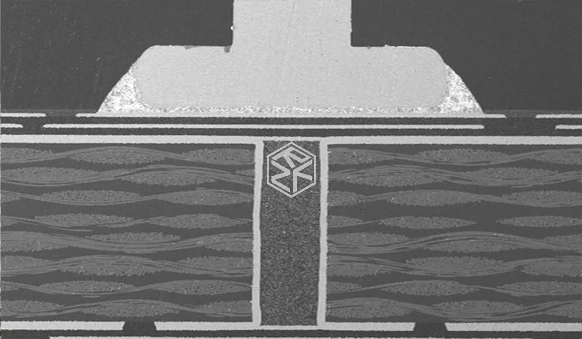
The leading edge of a gold-fingered PCB is beveled at an angle (typically 30°–45°) to allow smooth insertion into a socket. This bevel cuts through the gold, nickel, copper, and into the laminate substrate itself. The bevel is often the point of failure on high-frequency boards because it exposes the laminate edge to mechanical stress.
2.4 The Plating Process Sequence
For a standard FR4 board, the gold finger process flow is:
1. Fabricate PCB with exposed copper pads at the edge
2. Apply plating tape to protect non-finger areas
3. Electroplate nickel (current applied, ions deposited)
4. Electroplate hard gold over nickel
5. Remove tape
6. Route board to final outline
7. Bevel the edge at specified angle
Each of these steps interacts differently with high-frequency laminates.
3. High-Frequency Laminate Properties That Matter
To understand why gold fingers are problematic—or sometimes acceptable—we must understand the materials themselves. "High-frequency PCB" is not a single material but a family of laminates with distinct chemistries.
3.1 The Three Main Laminate Families
| Family | Examples | Dk @ 10GHz | Df @ 10GHz | Key Property | Gold Finger Compatibility |
|---|---|---|---|---|---|
| Hydrocarbon-Ceramic | Rogers 4003C, 4350B | 3.38–3.66 | 0.0027–0.0037 | Rigid, FR4-like processing | Moderate (feasible with care) |
| PTFE/Woven Glass | Rogers RT/duroid 5870/5880 | 2.20–2.33 | 0.0009–0.0012 | Extremely low loss, very soft | Poor (delamination risk) |
| PTFE/Ceramic | Rogers RO3000 series | 3.00–10.2 | 0.0010–0.0025 | High Dk options | Poor to moderate |
| Thermoset/Glass | Isola Astra MT77, Panasonic Megtron 6 | 3.5–4.0 | 0.002–0.004 | Balanced performance | Good (closest to FR4) |
3.2 Why PTFE Laminates Are Challenging for Plating
PTFE (polytetrafluoroethylene, Teflon) has three properties that conflict with gold finger processing:
First, surface energy. PTFE has one of the lowest surface energies of any solid (18–20 dynes/cm). For comparison, copper requires adhesion to surfaces with >40 dynes/cm for reliable plating. This is why PTFE PCBs require sodium etching or plasma treatment before any electroless copper deposition—and even then, adhesion is weaker than on FR4. The nickel and gold layers plated onto a PTFE edge are mechanically fragile.
Second, compliance. PTFE is soft. Under the mechanical stress of beveling and repeated insertion, PTFE deforms plastically. The nickel/gold layer, being rigid, cannot accommodate this deformation. The result is micro-cracking of the gold finger, exposing the underlying nickel to oxidation and increasing contact resistance over time.
Third, thermal expansion. PTFE has a coefficient of thermal expansion (CTE) of approximately 200–250 ppm/°C in the Z-axis. Nickel is 13 ppm/°C. During soldering or environmental temperature cycling, this mismatch creates shear stress at the nickel-PTFE interface, leading to delamination.
3.3 Hydrocarbon-Ceramic Laminates: The Pragmatic Middle Ground
Rogers 4000 series laminates use a hydrocarbon resin filled with ceramic particles, not PTFE. This chemistry provides:
• Surface energy >45 dynes/cm (platable without special treatment)
• CTE of 30–50 ppm/°C (compatible with nickel)
• Rigidity similar to FR4
For these reasons, if a high-frequency design absolutely requires gold fingers, Rogers 4000 series is the most practical choice. The performance penalties (discussed below) are manageable.
4. The Signal Integrity Impact: What Happens at the Edge
Adding gold fingers to any transmission line—microstrip, stripline, or coplanar waveguide—introduces a discontinuity at the PCB edge. The magnitude of this discontinuity depends on frequency, laminate properties, and gold finger geometry.
4.1 The Electromagnetic Mechanism
A perfect transmission line has uniform characteristic impedance (Z0) along its entire length. When the signal reaches the PCB edge and transitions into the gold finger region, three things change simultaneously:
1. Conductor geometry: The trace widens from its standard width (e.g., 0.5mm for 50Ω microstrip on Rogers 4350B) to the gold finger pad width (typically 0.8–1.5mm). Wider conductor = lower impedance.
2. Reference plane distance: At the very edge of the board, the ground plane underneath the trace terminates. Without a continuous ground reference, the signal becomes fringing field-dominated, increasing impedance.
3. Capacitive loading: The gold finger sits above the socket contact, creating an air-dielectric capacitor to the mating contact.
The net effect is usually a capacitive discontinuity (lower impedance followed by higher impedance), which creates signal reflection. In the time domain, this appears as a "glitch" in the TDR waveform.
4.2 Quantifying the Impact: Simulation and Measurement Data
Using 3D electromagnetic simulation (Ansys HFSS), we can quantify the effect on a typical 50Ω microstrip on Rogers 4350B at 28GHz (a common 5G n257/n258 band frequency).
Baseline (no gold finger, ideal termination):
• Return loss: -22 dB (VSWR 1.17)
• Insertion loss: 0.35 dB/cm
With standard gold finger (45° bevel, no compensation):
• Return loss: -12 dB (VSWR 1.67) — marginal, some systems fail at -14dB
• Insertion loss: 0.43 dB/cm (+0.08 dB penalty)
With optimized gold finger (30° bevel, widened pad, ground clearance adjustment):
• Return loss: -19 dB (VSWR 1.26) — well within typical spec
• Insertion loss: 0.41 dB/cm (+0.06 dB penalty)
The 30° bevel reduces the effective length of the discontinuity, while pad and ground adjustments compensate the capacitance shift. Optimization works, but it requires case-by-case simulation.
4.3 Frequency Dependence: Where It Matters Most
The impact of gold finger discontinuity scales with frequency. Below 3GHz, the effect is often negligible (return loss degradation <1dB). Above 10GHz, it becomes significant. At millimeter-wave frequencies (30GHz+), even a 0.5mm discontinuity is electrically long—approximately 5% of a wavelength—and can degrade system performance noticeably.
Rule of thumb: For designs below 6GHz (Wi-Fi 6, sub-6GHz 5G), gold fingers are generally acceptable with basic optimization. For designs above 28GHz (millimeter-wave 5G, automotive radar, point-to-point radio), either avoid gold fingers or invest in full-wave simulation.
5. Manufacturing Process Conflicts: A Step-by-Step Analysis
Beyond signal integrity, the physical act of fabricating gold fingers on high-frequency laminates presents unique manufacturing challenges.
5.1 Step 1: Drilling and Registration
High-frequency laminates often have soft, fibrous, or ceramic-filled compositions that behave differently under drill bits than FR4. PTFE, in particular, produces "smear"—melted polymer that coats hole walls and must be removed via plasma etch. Gold finger processing does not involve drilling, but the overall board registration (aligning the finger pads to the edge route) requires precision. Misregistration of ±50μm can cause gold fingers to be partially cut off during routing.
5.2 Step 2: Plating Tape Application
To selectively plate only the finger areas, the entire board is covered with plating tape except the gold finger pads. The tape must adhere firmly to the laminate surface during the aggressive electroplating bath (agitation, elevated temperature, chemical exposure).
On PTFE laminates, standard tapes do not adhere well. Special plasma-treated PTFE or high-tack tapes are required—and even then, edge lifting occurs in >5% of boards. On hydrocarbon-ceramic laminates (Rogers 4000), adhesion is similar to FR4.
5.3 Step 3: Nickel Electroplating
The nickel bath operates at 50–60°C with continuous agitation and current densities of 2–4 A/dm². The laminate edge is fully immersed.
The risk: On soft laminates (PTFE), the nickel layer plates onto a flexible surface. When the board cools and dries, residual stress in the nickel film (typically 50–100 MPa tensile) can cause peeling or blistering at the laminate interface. Rejection rates for PTFE boards with gold fingers can exceed 30% in poorly controlled processes.
5.4 Step 4: Hard Gold Electroplating
The hard gold bath (acidic, containing cobalt or nickel salts) operates at similar temperatures. Hard gold has even higher residual stress (150–200 MPa). The combination of nickel and gold residual stresses often exceeds the adhesion strength of PTFE laminates.
5.5 Step 5: Routing (Board Edge Profiling)
After plating, the board is routed to its final outline. The routing bit cuts through the gold, nickel, copper, and laminate. On soft laminates, the bit can pull or fray the laminate edge, creating a rough surface that compromises the bevel.
5.6 Step 6: Beveling
The beveling process uses a shaped grinding wheel or a V-groove router bit to cut the chamfer. This is the most mechanically aggressive step. The bevel depth (typically 1–2mm from the edge) cuts into the laminate.
Failure modes specific to high-frequency laminates:
• PTFE: The soft material smears or tears rather than cleanly beveling, creating a rough edge that does not seat properly in the socket.
• Ceramic-filled: The abrasive ceramic particles (silica or alumina) accelerate wear on the beveling tool, causing inconsistent angles across a panel.
• FR4 hybrid: The CTE mismatch between FR4 and high-frequency layers can cause micro-cracking at the bevel interface after thermal cycling.
6. When Do You Actually Need Gold Fingers on a High-Frequency Board?
Given the challenges, the engineering question becomes: Is the removable connection worth the signal integrity and manufacturing compromises?
6.1 The Case FOR Gold Fingers
Gold fingers are justified in specific scenarios:
Field-replaceable modules. If your high-frequency board will be replaced in the field by a technician with minimal tools (e.g., a radio module in a base station, a filter bank in a test instrument), a socketed connection with gold fingers is vastly preferable to soldering. The increased unit cost is amortized over the lifecycle of the system.
Test and calibration boards. High-frequency test fixtures, VNA calibration standards, and probe interface boards are inserted and removed hundreds of times. Gold fingers (or their planar counterpart, "pad array" connectors) are essential.
Daughter cards on a backplane. Some system architectures use a high-frequency backplane with multiple plug-in daughter cards (e.g., phased array radar beamforming modules). Gold fingers on the daughter cards allow modular reconfiguration.
6.2 The Case AGAINST Gold Fingers
Avoid gold fingers in these situations:
PTFE-based designs. If your application requires the ultra-low loss of PTFE (RT/duroid 5880, for example), gold fingers are not recommended. The combination of poor adhesion, soft substrate, and thermal mismatch yields unacceptable reliability. Use compression mount connectors instead.
Frequencies above 40GHz. At millimeter-wave frequencies, any discontinuity longer than 0.2mm begins to matter. The gold finger region is typically 3-5mm long—electrically, a significant obstacle. Edge-launch connectors (e.g., 2.92mm, 1.85mm, or 1.0mm coax) are superior.
High-volume, low-cost products. If you are manufacturing 10,000+ units, the 15-30% cost adder for gold fingers and the lower yield on high-frequency laminates may be prohibitive. A soldered flexible cable or board-to-board connector system may be cheaper overall.
Extreme temperature or vibration environments. Gold fingers are mechanically robust for insertion cycles but are not locking connectors. In high-vibration environments (aerospace, automotive engine compartments), gold fingers can work loose over time. Use threaded or latching connectors.
6.3 The Alternatives
When gold fingers are unsuitable, consider these alternatives:
| Alternative | Best For | Signal Integrity | Cost | Durability |
|---|---|---|---|---|
| Compression mount (e.g., Rosenberger, Samtec) | mmWave, PTFE laminates | Excellent (no discontinuity) | High | High (no wear) |
| Edge-launch coax connector | High-frequency test ports | Excellent | Medium | Medium (fragile) |
| Board-to-board mezzanine (e.g., Samtec SEARAY) | Digital + RF hybrid | Good (shielded options) | Medium | High |
| Soldered flex cable | Internal module connections | Very good | Low | High (soldered) |
| Anisotropic conductive film (ACF) | Fine pitch, permanent assembly | Moderate | Medium | Low |
For most high-frequency designs that truly require a removable interface, compression mount connectors offer the best signal integrity. A elastomeric or spring-loaded contact presses against a plain ENIG pad (not a gold finger), creating a connection without exposing the laminate edge to mechanical stress. The downside is higher cost and taller profile.
7. Design Guidelines: If You Must Use Gold Fingers
If after analyzing the trade-offs you conclude that gold fingers are necessary, follow these design and procurement guidelines to maximize success.
7.1 Laminate Selection Checklist
• Choose hydrocarbon-ceramic (Rogers 4000 series) over PTFE whenever possible.
• If PTFE is mandatory, consider a hybrid stack-up with FR4 or Rogers 4000 in the edge connector zone only.
• Verify with your fabricator that they have successfully plated gold fingers on your chosen material.
7.2 Geometry Optimization
• Bevel angle: Specify 30° ±5°, not 45°. Provide a detailed bevel drawing.
• Pad width: Widen the gold finger pad by 10-15% relative to the trace width to compensate for edge capacitance. (Simulation required for exact value.)
• Ground plane: Pull back the ground plane under the finger pads by 0.5–1.0mm. This increases edge impedance to counteract the pad capacitance.
• Finger spacing: Maintain at least 0.5mm between gold finger pads to reduce crosstalk. At high frequencies, adjacent fingers become coupled microstrip lines.
7.3 Process Specifications
Include these notes in your fabrication drawing:
• "Gold fingers: 0.5μm hard gold over 3μm nickel. Cobalt-hardened gold per MIL-DTL-45204."
• "Bevel angle: 30° ±5°, chamfer depth 1.0mm ±0.2mm."
• "No solder mask within 0.5mm of gold finger pads."
• "Impedance control required at gold finger interface. Supplier to provide TDR measurement at fingers."
7.4 Testing and Validation
Standard PCB electrical test (flying probe, bed of nails) does NOT test the gold finger interface after beveling. Request these additional tests:
• TDR at the fingers: Measure impedance at the edge connector pads. Compare to pre-bevel measurement.
• Contact resistance: After beveling, measure resistance through a mating socket (four-wire Kelvin method). Target <10mΩ per finger.
• Cross-section: For first article, request a micro-section through a gold finger to verify nickel and gold thickness and adhesion to laminate.
8. Summary and Decision Framework
So, does a high-frequency board need gold finger processing?
The short answer remains: Yes, but only under specific conditions and with careful optimization.
The longer, more useful answer is a decision matrix:
| Condition | Recommendation |
|---|---|
| Frequency <6GHz, Rogers 4000 laminate, >100 insertion cycles | Gold fingers acceptable with 30° bevel |
| Frequency <6GHz, PTFE laminate | Avoid gold fingers (use compression mount) |
| Frequency 6-28GHz, Rogers 4000 laminate, field-replaceable | Gold fingers possible—must simulate and optimize |
| Frequency 28-40GHz | Avoid gold fingers unless absolutely no alternative |
| Frequency >40GHz | Do not use gold fingers |
| High vibration environment | Do not use gold fingers (use locking connector) |
| Test/calibration board (frequent insertions) | Gold fingers recommended |
| High volume (>5000 units/year) | Evaluate cost of alternatives |
Final technical summary: Gold fingers on high-frequency boards are an acceptable engineering compromise for certain applications, not an ideal solution. The signal integrity penalty (approximately 2-3dB return loss degradation at 28GHz) is manageable if budgeted for in the link budget. The manufacturing yield risk (especially on PTFE) is significant and must be discussed with your fabricator early in the design process.
For most high-frequency designs, the best answer is not to ask "does this board need gold fingers" but rather "can this board use a compression mount or coax launch instead?" Only when the answer is no should you proceed down the gold finger path.
(Richfulljoy provides free DFM reviews for high-frequency designs. Contact our engineering team with your stack-up and frequency requirements.)
9. Frequently Asked Questions (FAQ)
Q1: Can Rogers 4000 series support gold finger processing?
A: Yes. Rogers 4003C and 4350B are the most compatible high-frequency laminates for gold fingers. Use 30° bevel angle and request impedance simulation from your fabricator.
Q2: Why is PTFE (RT/duroid) problematic for gold fingers?
A: PTFE has low surface energy (poor adhesion), high compliance (deforms under stress), and high CTE (thermal mismatch with nickel). These cause delamination, cracking, and plating failure.
Q3: Does gold finger processing affect signal impedance?
A: Yes. The transition from trace to pad creates a capacitive discontinuity. At 28GHz, return loss can degrade from -22dB to -12dB without optimization. Simulation-based compensation can recover to -19dB.
Q4: What bevel angle is optimal for high-frequency gold fingers?
A: 30° provides the best balance of signal integrity (2dB better return loss than 45°) and mechanical insertion reliability. Specify this in your fabrication drawing.
Q5: Can I combine ENIG for SMD pads and hard gold for edge fingers?
A: Yes (selective plating). The fabricator masks non-finger areas during gold plating. Adds 2-3 days lead time and 15-30% cost.
Q6: What is the cost impact of adding gold fingers to a high-frequency board?
A: Typically 15-30% higher than standard ENIG. For a 4-layer Rogers 4350B prototype (100x100mm), expect $50-$100 adder. Yield loss on PTFE can be higher.
Q7: Are there alternatives to gold fingers for removable high-frequency connections?
A: Yes. Compression mount connectors (e.g., Rosenberger, Samtec) offer excellent signal integrity without plating edge connectors. Higher cost but better performance above 28GHz.
Q8: How do I specify gold fingers correctly in my fabrication files?
A: Include in your drawing: location coordinates, bevel angle (30°), gold thickness (0.5μm over 3μm nickel), chamfer depth, and impedance requirement. Reference MIL-DTL-45204 for hard gold specification.
Q9: What testing should I request for gold-fingered high-frequency boards?
A: Request TDR impedance measurement at the fingers, four-wire contact resistance through mating socket, and micro-section cross-section for first article inspection.
Q10: For millimeter-wave designs (30GHz+), should I use gold fingers?
A: Generally no. The discontinuity becomes electrically significant. Use edge-launch coax connectors (2.92mm, 1.85mm, or 1.0mm) or compression mounts instead.
10. About RICHFULLJOY
RICHFULLJOY is a PCB manufacturer specializing in the production of high-frequency, radio frequency and microwave circuit boards. With over ten years of production experience in Rogers, Taconic, PTFE and hybrid laminated boards, we provide design support for manufacturing for engineers, helping them make rational material selections, control impedance, and deal with special processes such as gold fingers.









