











77GHz Automotive Radar PCB: The End of FR4 Hybrid Era — Production-Grade Antenna Boards Must Control Dk of Every Prepreg Layer
1. Executive Summary: The Industry Shift
For years, PCB manufacturers have relied on hybrid stack-ups — combining a thin layer of high-frequency laminate (Rogers or PTFE) on the outer layer for antenna patterning, with standard FR4 or mid-loss materials for the inner layers — to reduce costs on 24GHz automotive radar boards. This approach was acceptable for blind-spot detection and rear cross-traffic alerts at lower frequencies.
That era is now over for 77GHz front-radar and 4D imaging radar applications.
At 77GHz, the wavelength is approximately 3.9mm in air (and even shorter within dielectric materials). A variation in the dielectric constant (Dk) of just ±0.05 across a single prepreg (PP) sheet can shift the antenna resonant frequency by 100-200MHz — enough to push the radar outside its legal operating band or degrade range resolution below functional safety requirements.
For automotive PCBs certified under IATF 16949:2016, the era of "close enough" hybrid mixing is finished. Production-grade antenna boards require batch-level Dk control verified for every prepreg layer, not just the core material.
2. Why 77GHz Changes Everything: The Physics of Millimeter-Wave Radar
2.1 The Wavelength Problem
The fundamental challenge at 77GHz is scale. Consider this comparison:
| Parameter | 24GHz Radar | 77GHz Radar | Ratio/Impact |
|---|---|---|---|
| Wavelength in air (λ0) | 12.5mm | 3.9mm | 3.2x smaller |
| Patch antenna length (λ/2) | ~6.0mm | ~1.9mm | 3.2x smaller |
| Phase error from ΔDk=0.05 (over 10mm) | ~14° | ~45° | 3.2x larger |
| Range resolution (BW=200MHz vs 4GHz) | 75cm | 4cm | 77GHz is 20x better |
| Insertion loss per cm (Rogers 3003) | ~0.15 dB | ~0.45 dB | 3x higher |
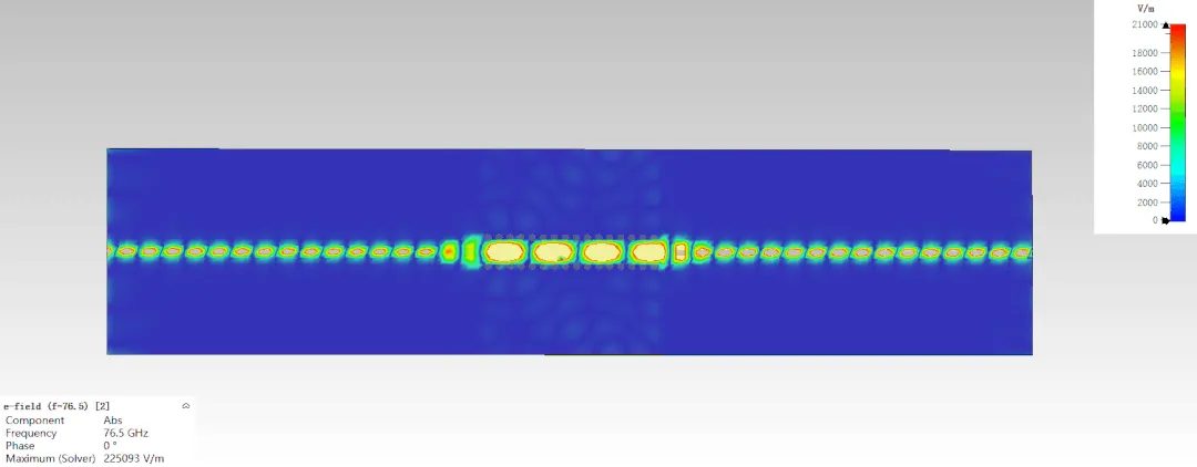
At 77GHz, a 0.5mm misalignment or a 0.02 variation in Dk between two adjacent prepreg sheets creates a phase error that degrades beamforming accuracy. For 4D imaging radar systems using multiple-input multiple-output (MIMO) arrays with 12 or 16 virtual channels, these small errors accumulate across the array, causing side-lobe elevation and reducing angular resolution.
2.2 The Functional Safety Context
Automotive radar is not a consumer product. It is a safety-critical sensor for:
Automatic Emergency Braking (AEB) — regulated by NCAP and NHTSA
Adaptive Cruise Control (ACC) — requires lane-level accuracy
Forward Collision Warning (FCW) — must trigger reliably
Highway Assist / Traffic Jam Pilot — Level 2+/Level 3 autonomy
The ISO 26262 functional safety standard requires that random hardware failures (including material-driven performance shifts) be controlled to <1 FIT (failure in time) for ASIL D systems. Uncontrolled Dk variation is a systematic failure mechanism — and systematic failures are not covered by ISO 26262 fault metrics. They must be eliminated through process control, not statistically mitigated. This is why IATF 16949 emphasizes "defect prevention" over "defect detection".
3. The Fallacy of "Hybrid FR4 Mixing" for 77GHz
3.1 Why This Fails at 77GHz
At 77GHz, the electromagnetic fields of a microstrip patch antenna extend significantly into the substrate below the patch, not just the top laminate. Specifically:
Approximately 60-70% of the field energy resides in the top laminate (Rogers)
Approximately 30-40% of the field energy resides in the prepreg layer immediately below
If that prepreg layer has an uncontrolled or inconsistent Dk, the effective Dk seen by the antenna varies unpredictably across production batches. The result:
| Issue | Consequence |
|---|---|
| Resonant frequency shift (f_res = c/(2L√ε_eff)) | Detuning outside 76-77GHz band → EIRP drop >3dB |
| Input impedance mismatch (S11 > -10dB) | Reduced radiated power → shorter detection range |
| Patch-to-patch phase variation across array | Grating lobes → false target detection |
| Temperature coefficient mismatch (TCDk) | Performance drift from -40°C to +125°C |
In one documented case, a manufacturer using hybrid FR4 prepreg for a 77GHz antenna array observed a f_shift of 280MHz between two production batches of the same design — enough to fail the customer's S11 specification of -12dB at 77GHz. The root cause was traced to a 0.09 variation in Dk of the prepreg layer between different prepreg lots.
3.2 The Market Trend: Moving Away from Hybrid
Industry data confirms the shift. The global high-frequency PCB for automotive radar market is projected to grow from $286M in 2024 to $832M by 2031 (16.1% CAGR). However, within this growth, the hybrid segment is slowing while full high-frequency stack-ups (all layers using controlled-Dk materials) are accelerating, driven by:
Long-range front radar (L2+ ADAS) demanding LCP/PTFE solutions
4D imaging radar requiring phase-coherent 16-channel arrays
EU NCAP radar standardization mandating consistent performance across vehicle platforms
Chinese NEV manufacturers (BYD, NIO, Xpeng) specifying full controlled-Dk stack-ups in their RFQ documents
4. IATF 16949 Requirements for 77GHz Radar PCB Manufacturing
4.1 Overview of IATF 16949:2016
IATF 16949:2016 is the global quality management standard for automotive component suppliers. It supersedes ISO/TS 16949 and is mandatory for any PCB supplier to the Tier-1 automotive market. Key clauses relevant to high-frequency PCB manufacturing include:
| Clause | Requirement | Application to 77GHz Radar PCB |
|---|---|---|
| 8.3.3.3 | Product design with special characteristics | Dk, Df, and impedance are "special characteristics" (SC/CC) |
| 8.4.2.2 | Supplier quality management | Raw material (prepreg/core) suppliers must be IATF-certified |
| 8.5.1.1 | Control plan for manufacturing | Specific control methods for lamination temperature, pressure, and prepreg handling |
| 9.1.1.1 | Statistical tools (CPK/PPK) | Dk variation must be controlled to CPK ≥1.33 |
| 10.2.3 | Problem-solving (8D) | Any nonconformance (e.g., impedance drift) requires 8D documentation |
4.2 PPAP (Production Part Approval Process) — Level 3 Requirements
PPAP Level 3 is the most common submission level for automotive radar PCBs. It requires 18 documented elements, including:
Critical for 77GHz Radar:
Design Record — Full stack-up drawing with Dk/Df specified for every dielectric layer (core AND prepreg), including tolerance (±0.02 or better)
Process Flow Diagram — Must identify "special characteristic" control points
Control Plan — For each step: lamination, etching, impedance testing, final inspection
Dimensional Results — Line width tolerance (typically ±10μm for 77GHz), registration (±25μm)
Material Test Results — Certificate of Analysis (COA) for every prepreg lot, including Dk measurement at 10GHz or 77GHz
Performance Test Results — TDR impedance coupon data, S-parameter (VNA) data for antenna layer
IMDS (International Material Data System) — Full material declaration for ELV and REACH compliance
Certificate of Conformance (COC) — Signed certification that the batch meets all specifications
4.3 Dk Control as a "Special Characteristic"
Under IATF 16949, any parameter that affects safety or regulatory compliance must be designated as a Special Characteristic:
CC (Critical Characteristic) — Directly affects safety (e.g., impedance consistency for AEB radar)
SC (Significant Characteristic) — Affects form, fit, function (e.g., Dk tolerance, copper adhesion)
For 77GHz radar PCBs, the Dk of each prepreg layer must be treated as an SC or CC. This means:
Incoming inspection of every prepreg lot with Dk measurement (not just relying on supplier COA)
Statistical process control (SPC) charts for lamination parameters
Traceability from raw material lot to finished PCB serial number
Annual layout (re-qualification) of the process
4.4 Documentation Hierarchy for 77GHz Radar PCB
The following documents are required for an IATF 16949-compliant 77GHz radar program:
| Document | Frequency | Owner |
|---|---|---|
| Material COA (cores + prepregs) | Per lot | Material supplier |
| Dk verification test report | Per lot | PCB manufacturer |
| Impedance coupon TDR report | Per panel | PCB manufacturer |
| VNA S-parameter plot | Per production batch | PCB manufacturer |
| PPAP Level 3 submission | Initial + annual | PCB manufacturer |
| IMDS declaration | Per material change | PCB manufacturer |
| 8D report | Per nonconformance | PCB manufacturer |
| Run@Rate (capacity study) | Initial + annual | PCB manufacturer |
5. Material Solutions for 77GHz Automotive Radar
5.1 Laminate Materials (Cores)
Several material families are suitable for 77GHz radar antenna layers:
| Material | Dk @77GHz | Df @77GHz | TCDk (ppm/°C) | Key Feature | Automotive Adoption |
|---|---|---|---|---|---|
| Rogers RO3003G2 | 3.07 | 0.0010 | -3 | Industry standard; VLP ED copper | High (Tier-1 standard) |
| Rogers RO4835 | 3.48 | 0.0037 | -40 | Lower cost; hydrocarbon | Medium |
| AGC TSM-DS3 | 3.00 | 0.0011 | -9 | PTFE/ceramic blend | Medium |
| Panasonic Megtron 6 | 3.7 | 0.0020 | -50 | Thermoset; FR4-like processing | Growing |
| Isola Astra MT77 | 3.7 | 0.0019 | -50 | High-Tg thermoset | Growing |
RO3003G2 is the most widely adopted for 77GHz front radar, with specific advantages:
Ceramic-filled PTFE with VLP (Very Low Profile) ED copper — reduces conductor loss vs. standard ED copper
Dk of 3.00 ±0.04 at 10GHz (3.07 ±0.04 at 77GHz) — tighter tolerance than RO3003 (previous gen)
Enhanced filler system reduces dielectric porosity — better consistency across panels
5.2 Prepreg Materials for 77GHz — The Critical Layer
Standard FR4-type prepregs (e.g., 1080, 2116 glass styles with epoxy resin) have:
Dk typically specified only as "4.2-4.5" (no tight tolerance)
Df of 0.012-0.018 (too high for 77GHz)
Significant Dk variation with resin content and glass distribution
For 77GHz production, manufacturers must use controlled-Dk prepregs:
| Prepreg | Dk | Df | Type | Application |
|---|---|---|---|---|
| AGC fastRise FR-25-0021-45 | 2.43 | 0.0012 | Non-reinforced (no glass) | Bonding PTFE layers; laser-ablatable for HDI |
| AGC Meteorwave 8300 | 3.0 ±0.05 | 0.0025 | PPE (glass-reinforced) | Hybrid stacks; high-Tg FR4 processing |
| Rogers RO4450T | 3.2 | 0.0040 | Hydrocarbon | Bonding RO4000 series |
| Taconic TPG-35 | 3.5 | 0.0035 | PTFE/ceramic | Bonding PTFE cores |
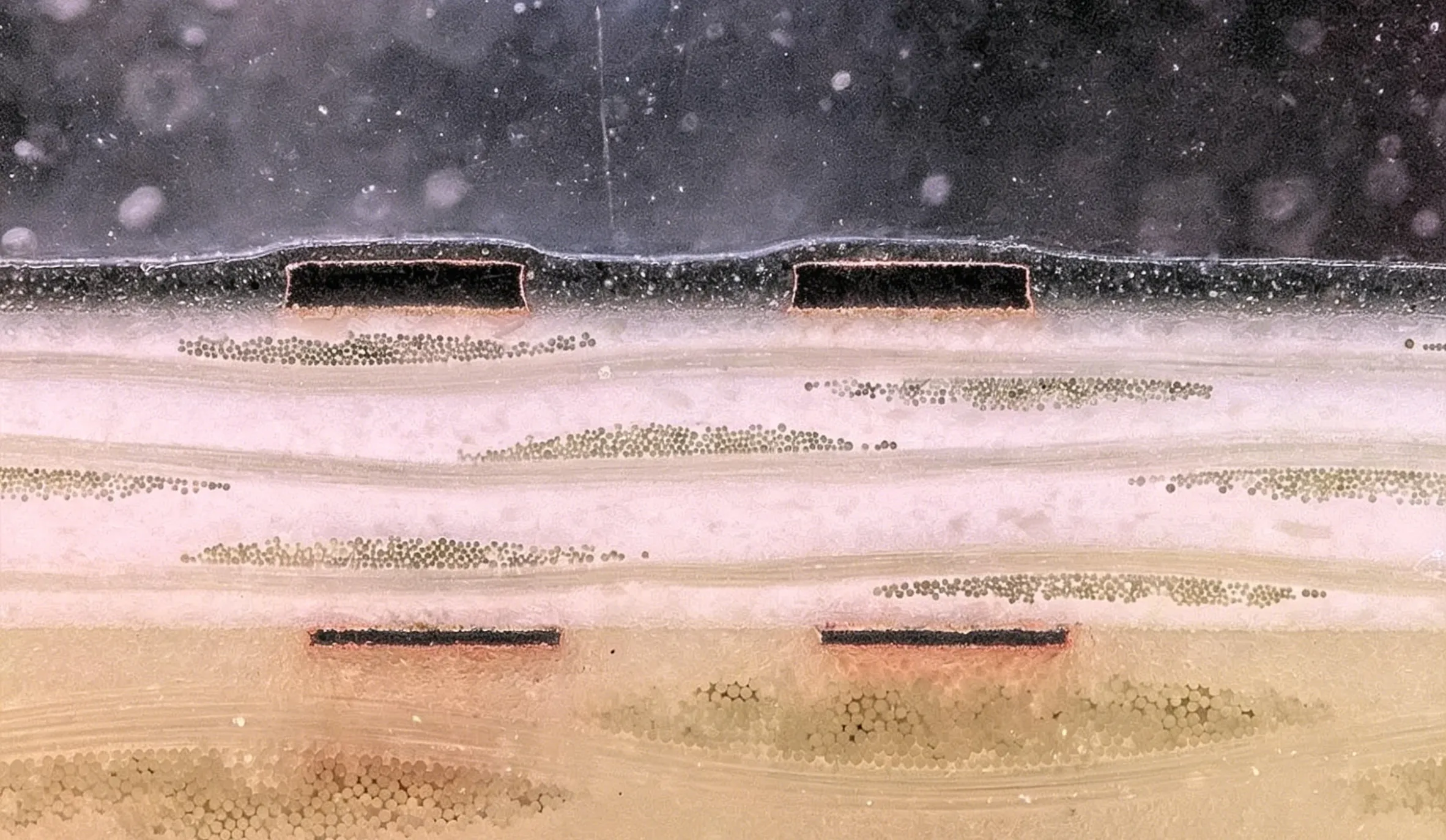
Key point: fastRise FR-25-0021-45 is uniquely suited for 77GHz because it is non-reinforced (no fiberglass weave). Woven glass prepregs create fiber weave effect (FWE) — a periodic Dk variation at the scale of the glass bundle spacing. At 77GHz, FWE causes phase ripple across the antenna array, degrading beamforming. Non-reinforced prepregs eliminate this issue entirely.
5.3 Hybrid Stack-Ups That Actually Work at 77GHz
Not all hybrid stack-ups are obsolete. The following configuration is acceptable for 77GHz, provided every prepreg layer has controlled Dk:
Layer 1 (Antenna): Rogers RO3003G2 (0.127mm, 1/2oz VLP copper)
Layer 2: fastRise FR-25-0021-45 prepreg (0.050mm, Dk=2.43 controlled)
Layer 3: Ground (1/2oz copper)
Layer 4: Meteorwave 8300 prepreg (Dk=3.0±0.05)
Layer 5: FR4 core (non-critical power/ground layers)
... (remaining layers)
This stack-up:
Keeps the antenna field within controlled-Dk materials (RO3003G2 + fastRise)
Uses non-reinforced prepreg for the critical bonding layer to eliminate FWE
Allows lower-cost FR4 for non-RF layers
Maintains CAF resistance and thermal reliability
6. Process Control Points for 77GHz Radar PCB Manufacturing
6.1 Incoming Material Control
| Step | Control Method | Acceptance Criteria |
|---|---|---|
| Core Dk verification | Stripline resonator test (per IPC-TM-650 2.5.5.5) | Dk within supplier spec ±0.03 |
| Prepreg Dk verification | Clamped stripline method | Dk within spec ±0.05 |
| Copper foil roughness (Rz) | Profilometer | Rz ≤4μm for VLP foil |
| Resin content (prepreg) | Burnout test (per IPC-TM-650 2.3.16) | Within datasheet limit ±2% |
| Gel time (prepreg) | Hot plate method | Within datasheet limit ±5 sec |
6.2 Lamination Process — Special Characteristic Control
Lamination is the most critical step for Dk consistency. Parameters affecting Dk:
| Parameter | Effect on Dk | Control Target | SPC Chart |
|---|---|---|---|
| Ramp rate | Resin flow → Dk variation | 1.5-3.0°C/min | Xbar-R |
| Peak temperature | Crosslink density | Tg + 20-30°C | Xbar-R |
| Pressure at gel | Thickness (dielectric constant inversely related) | 300-400 PSI | Xbar-R |
| Cool-down rate | Stress (affects Dk stability) | ≤5°C/min | Xbar-R |
For 77GHz radar, post-lamination thickness measurement of every panel is required. Target thickness tolerance: ±5% or better.
6.3 Etching and Line Width Control
At 77GHz, patch antenna dimensions are ~1.9mm × 1.9mm (for λ/2 patch). A line width variation of ±10μm creates a frequency shift of approximately 50-80MHz.
Control requirements:
Etch factor (ratio of etch depth to undercut): Target ≥3.0
Line width tolerance: ±10μm for antenna layer (special characteristic)
Registration (layer-to-layer): ±25μm for RF layers
Copper thickness variation: ±10% of nominal
6.4 Impedance and Electrical Testing
IATF 16949 requires 100% testing of special characteristics where feasible. For 77GHz radar PCBs:
| Test | Method | Coverage | Acceptance |
|---|---|---|---|
| Differential impedance (RF traces) | TDR (coupon or panel) | Per panel | Target ±5% (not ±10%) |
| Antenna S11 (return loss) | VNA with probe station | Per batch | ≤-12dB at 76-77GHz |
| Insertion loss | VNA (2-port) | Per batch | Within simulation ±0.1dB/cm |
| Microstrip impedance | TDR | Per panel | 50Ω ±5% |
Note: Many PCB suppliers use ±10% impedance tolerance for standard RF boards. For 77GHz automotive radar, IATF 16949 auditors expect ±5% or tighter for antenna feedlines.
6.5 Traceability Requirements
Every 77GHz radar PCB must be traceable to:
Prepreg lot number (for each PP sheet used)
Core lot number
Lamination batch (oven ID, operator, date/time)
Impedance coupon data
7. Summary: The New Standard for 77GHz Radar PCBs
The industry has crossed a threshold. 24GHz hybrid designs — with uncontrolled FR4 prepreg — are not migrating successfully to 77GHz. The physics of millimeter-wave propagation, combined with IATF 16949's defect-prevention requirements, demand a new approach.
Production-grade 77GHz automotive radar PCBs require:
Full Dk control of every dielectric layer — including prepreg — with tolerances of ±0.05 or better
Controlled-Dk prepreg materials — preferably non-reinforced (fastRise type) for critical antenna bonding layers
IATF 16949:2016 certification with documented PPAP Level 3 submission
CPK ≥1.33 on all special characteristics (Dk, impedance, line width)
100% TDR or VNA testing of impedance for every production panel
Full traceability from prepreg lot to finished PCB serial number
Decision matrix for material selection:
| Application | Recommended Top Laminate | Recommended Prepreg (Bonding) | FR4 Acceptable? |
|---|---|---|---|
| Long-range front radar (77GHz) | RO3003G2 | fastRise FR-25-0021-45 | No — uncontrolled Dk |
| 4D imaging radar (76-81GHz) | RO3003G2 or TSM-DS3 | fastRise or Meteorwave | No — phase coherence required |
| Corner/short-range radar (77GHz, lower performance) | RO4835 or Megtron 6 | Meteorwave 8300 | Conditional — only for non-RF inner layers |
| 24GHz (legacy) | RO4350B | Standard FR4 prepreg | Yes — acceptable with IATF controls |
The era of "close enough" hybrid mixing is finished. For 77GHz automotive radar, every prepreg layer matters. Richfulljoy's IATF 16949-certified production line supports full material traceability, PPAP Level 3 documentation, and CPK-controlled manufacturing for 77GHz and 79GHz radar PCBs.
Contact our automotive engineering team for DFM review and stack-up simulation — free for qualified ADAS programs.
8. Frequently Asked Questions
Q1: Why is FR4 not acceptable for 77GHz radar PCB prepreg layers?
A: FR4 prepreg has uncontrolled Dk (typically specified only as "4.2 typical" with no tolerance) and high Df (0.012-0.018). At 77GHz, this causes resonant frequency shifts of 200MHz+ and insertion loss >0.5dB/cm, degrading radar range and angular resolution.
Q2: What is PPAP Level 3 and why is it required for automotive radar PCBs?
A: PPAP (Production Part Approval Process) Level 3 is the standard documentation package required by IATF 16949 for automotive components. It includes 18 elements: design records, control plan, material test results, performance test results, IMDS, and COC. Required for every new automotive radar PCB program.
Q3: Can hybrid stack-ups (Rogers + FR4) work at 77GHz?
A: Only if the prepreg bonding the Rogers layer has controlled Dk (e.g., fastRise or Meteorwave). Standard FR4 prepreg is unacceptable because ~40% of antenna field energy resides in this layer, making Dk variation directly impact resonant frequency.
Q4: What is the typical Dk tolerance required for 77GHz radar PCBs?
A: For production-grade boards, ±0.03-0.05 on each dielectric layer (both core and prepreg). Tighter tolerance (±0.02) may be required for 4D imaging radar with 16+ channel arrays.
Q5: What is fiber weave effect (FWE) and why does it matter at 77GHz?
A: FWE is periodic Dk variation caused by the glass bundle spacing in woven prepregs. At 77GHz, this creates phase ripple across antenna arrays. Non-reinforced prepregs (fastRise) eliminate FWE entirely.
Q6: What impedance tolerance does IATF 16949 require for 77GHz radar?
A: While standard RF tolerance is ±10%, IATF 16949 auditors typically expect ±5% for 77GHz radar antenna feedlines due to functional safety implications for AEB and ACC systems.
Q7: Does Richfulljoy provide PPAP Level 3 documentation for 77GHz radar PCBs?
A: Yes. Richfulljoy provides full PPAP Level 3 documentation including design record, control plan, material COAs, Dk verification, TDR reports, VNA S-parameter data, IMDS declaration, and COC for every automotive radar PCB program.
Q8: What is the lead time for IATF 16949-certified 77GHz radar PCB production?
A: Prototype (5-10 panels): 7-10 business days. Production (100-1000 panels): 15-20 business days after PPAP approval.
Q9: Can you combine ENIG for SMD pads and hard gold for edge fingers on 77GHz radar boards?
A: Generally not recommended. Edge gold fingers are rare on 77GHz radar (most use compression mounts). If required, selective plating is possible but adds cost and may impact impedance at the board edge.
Q10: How do I specify Dk control requirements in my fabrication drawing for 77GHz radar?
A: Include: "All dielectric layers (cores AND prepregs) shall have Dk verified per IPC-TM-650 2.5.5.5 with tolerance ±0.05. Supplier to provide Dk measurement report for each prepreg lot. Dk designated as Significant Characteristic (SC) per IATF 16949."









